LM4050
Precision Micropower Shunt Voltage Reference
General Description
Ideal for space critical applications, the LM4050 precision
voltage reference is available in the sub-miniature (3 mm x
1.3 mm) SOT-23 surface-mount package. The LM4050's de-
sign eliminates the need for an external stabilizing capacitor
while ensuring stability with any capacitive load, thus making
the LM4050 easy to use. Further reducing design effort is the
availability of several fixed reverse breakdown voltages:
2.500V, 4.096V, 5.000V, 8.192V, and 10.000V. The minimum
operating current increases from 60 µA for the LM4050-2.5
to 100 µA for the LM4050-10.0. All versions have a maximum
operating current of 15 mA.
The LM4050 utilizes fuse and zener-zap reverse breakdown
voltage trim during wafer sort to ensure that the prime parts
have an accuracy of better than
±
0.1% (A grade) at 25∞C.
Bandgap reference temperature drift curvature correction
and low dynamic impedance ensure stable reverse break-
down voltage accuracy over a wide range of operating tem-
peratures and currents.
All grades and voltage options of the LM4050 are available
in both an industrial temperature range (-40∞C and +85∞C)
and an extended temperature range (-40∞C and +125∞C).
Features
n
Small packages: SOT-23
n
No output capacitor required
n
Tolerates capacitive loads
n
Fixed reverse breakdown voltages of 2.500V, 4.096V,
5.000V, 8.192V, and 10.000V
Key Specifications (LM4050-2.5)
j
Output voltage tolerance
(A grade, 25∞C)
±
0.1% (max)
j
Low output noise
(10 Hz to 10 kHz)
41 µV
rms
(typ)
j
Wide operating current range
60 µA to 15 mA
j
Industrial temperature range
-40∞C to +85∞C
j
Extended temperature range
-40∞C to +125∞C
j
Low temperature coefficient
50 ppm/∞C (max)
Applications
n
Portable, Battery-Powered Equipment
n
Data Acquisition Systems
n
Instrumentation
n
Process Control
n
Energy Management
n
Product Testing
n
Automotive
n
Precision Audio Components
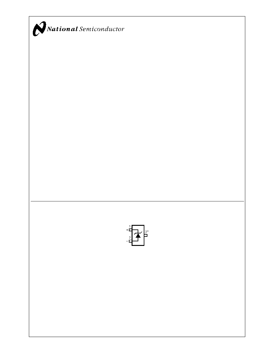
Connection Diagram
SOT-23
10104501
*This pin must be left floating or connected to pin 2.
Top View
See NS Package Number MF03A
May 2002
LM4050
Precision
Micropower
Shunt
V
oltage
Reference
© 2002 National Semiconductor Corporation
DS101045
www.national.com

Ordering Information
Industrial Temperature Range (-40∞C to +85∞C)
Reverse Breakdown
Voltage Tolerance at 25∞C and Average
Reverse Breakdown
Voltage Temperature Coefficient
LM4050 Supplied as 1000 Units,
Tape and Reel
LM4050 Supplied as 3000 Units,
Tape and Reel
±
0.1%, 50 ppm/∞C max (A grade)
LM4050AIM3-2.5
LM4050AIM3X-2.5
LM4050AIM3-4.1
LM4050AIM3X-4.1
LM4050AIM3-5.0
LM4050AIM3X-5.0
LM4050AIM3-8.2
LM4050AIM3X-8.2
LM4050AIM3-10
LM4050AIM3X-10
±
0.2%, 50 ppm/∞C max (B grade)
LM4050BIM3-2.5
LM4050BIM3X-2.5
LM4050BIM3-4.1
LM4050BIM3X-4.1
LM4050BIM3-5.0
LM4050BIM3X-5.0
LM4050BIM3-8.2
LM4050BIM3X-8.2
LM4050BIM3-10
LM4050BIM3X-10
±
0.5%, 50 ppm/∞C max (C grade)
LM4050CIM3-2.5
LM4050CIM3X-2.5
LM4050CIM3-4.1
LM4050CIM3X-4.1
LM4050CIM3-5.0
LM4050CIM3X-5.0
LM4050CIM3-8.2
LM4050CIM3X-8.2
LM4050CIM3-10
LM4050CIM3X-10
Extended Temperature Range (-40∞C to +125∞C)
Reverse Breakdown
Voltage Tolerance at 25∞C and Average
Reverse Breakdown
Voltage Temperature Coefficient
LM4050 Supplied as 1000 Units,
Tape and Reel
LM4050 Supplied as 3000 Units,
Tape and Reel
±
0.1%, 50 ppm/∞C max (A grade)
LM4050AEM3-2.5
LM4050AEM3X-2.5
LM4050AEM3-4.1
LM4050AEM3X-4.1
LM4050AEM3-5.0
LM4050AEM3X-5.0
LM4050AEM3-8.2
LM4050AEM3X-8.2
LM4050AEM3-10
LM4050AEM3X-10
±
0.2%, 50 ppm/∞C max (B grade)
LM4050BEM3-2.5
LM4050BEM3X-2.5
LM4050BEM3-4.1
LM4050BEM3X-4.1
LM4050BEM3-5.0
LM4050BEM3X-5.0
LM4050BEM3-8.2
LM4050BEM3X-8.2
LM4050BEM3-10
LM4050BEM3X-10
±
0.5%, 50 ppm/∞C max (C grade)
LM4050CEM3-2.5
LM4050CEM3X-2.5
LM4050CEM3-4.1
LM4050CEM3X-4.1
LM4050CEM3-5.0
LM4050CEM3X-5.0
LM4050CEM3-8.2
LM4050CEM3X-8.2
LM4050CEM3-10
LM4050CEM3X-10
LM4050
www.national.com
2
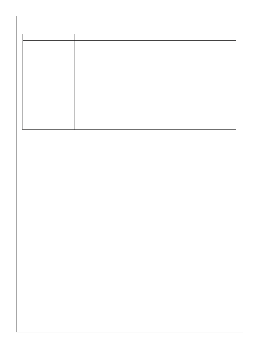
SOT-23 Package Marking Information
Only three fields of marking are possible on the SOT-23's small surface. This table gives the meaning of the three fields.
Part Marking
Field Definition
RCA
First Field:
RDA
R = Reference
REA
Second Field:
RFA
C = 2.500V Voltage Option
RGA
D = 4.096V Voltage Option
RCB
E = 5.000V Voltage Option
RDB
F = 8.192V Voltage Option
REB
G = 10.000V Voltage Option
RFB
RGB
Third Field:
RCC
A≠C = Initial Reverse Breakdown Voltage or Reference Voltage Tolerance
RDC
A =
±
0.1%, B =
±
0.2%, C = +0.5%,
REC
RFC
RGC
LM4050
www.national.com
3
Absolute Maximum Ratings
(Note 1)
If Military/Aerospace specified devices are required,
please contact the National Semiconductor Sales Office/
Distributors for availability and specifications.
Reverse Current
20 mA
Forward Current
10 mA
Power Dissipation (T
A
= 25∞C) (Note 2)
M3 Package
280 mW
Storage Temperature
-65∞C to +150∞C
Lead Temperature
M3 Package
Vapor phase (60 seconds)
+215∞C
Infrared (15 seconds)
+220∞C
ESD Susceptibility
Human Body Model (Note 3)
2 kV
Machine Model (Note 3)
200V
See AN-450 "Surface Mounting Methods and Their Effect
on Product Reliability" for other methods of soldering
surface mount devices.
Operating Ratings
(Note 2)
Temperature Range
(T
min
T
A
T
max
)
Industrial Temperature
Range
-40∞C
T
A
+85∞C
Extended temperature
Range
-40∞C
T
A
+125∞C
Reverse Current
LM4050-2.5
60 µA to 15 mA
LM4050-4.1
68 µA to 15 mA
LM4050-5.0
74 µA to 15 mA
LM4050-8.2
91 µA to 15 mA
LM4050-10.0
100 µA to 15 mA
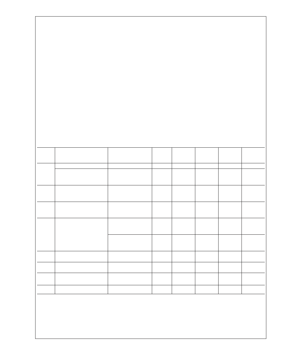
LM4050-2.5
Electrical Characteristics
Boldface limits apply for T
A
= T
J
= T
MIN
to T
MAX
; all other limits T
A
= T
J
= 25∞C. The grades A, B and C designate initial
Reverse Breakdown Voltage tolerances of
±
0.1%,
±
0.2%, and 0.5% respectively.
Symbol
Parameter
Conditions
Typical
(Note 4)
LM4050AIM3
LM4050AEM3
Limits
(Note 5)
LM4050BIM3
LM4050BEM3
Limits
(Note 5)
LM4050CIM3
LM4050CEM3
Limits
(Note 5)
Units
(Limit)
V
R
Reverse Breakdown Voltage
I
R
= 100 µA
2.500
V
Reverse Breakdown Voltage
Tolerance (Note 6)
I
R
= 100 µA
±
2.5
±
5.0
±
13
mV (max)
Industrial Temp. Range
±
11
±
14
±
21
mV (max)
Extended Temp. Range
±
15
±
18
±
25
mV (max)
I
RMIN
Minimum Operating Current
41
µA
60
60
60
µA (max)
65
65
65
µA (max)
V
R
/
T
Average Reverse Breakdown
Voltage Temperature Coefficient
(Note 6)
I
R
= 10 mA
±
20
ppm/∞C
I
R
= 1 mA
±
15
ppm/∞C
I
R
= 100 µA
±
15
±
50
±
50
±
50
ppm/∞C (max)
V
R
/
I
R
Reverse Breakdown Voltage
Change with Operating Current
Change (Note 7)
I
RMIN
I
R
1 mA
0.3
mV
0.8
0.8
0.8
mV (max)
1.2
1.2
1.2
mV (max)
1 mA
I
R
15 mA
2.3
mV
6.0
6.0
6.0
mV (max)
8.0
8.0
8.0
mV (max)
Z
R
Reverse Dynamic Impedance
I
R
= 1 mA, f = 120 Hz, I
AC
= 0.1 I
R
0.3
e
N
Wideband Noise
I
R
= 100 µA
41
µV
rms
10 Hz
f 10 kHz
V
R
Reverse Breakdown Voltage
Long Term Stability
t = 1000 hrs
T = 25∞C
±
0.1∞C
I
R
= 100 µA
120
ppm
V
HYST
Thermal Hysteresis
(Note 8)
T = -40∞C to 125∞C
0.7
mV
LM4050
www.national.com
4
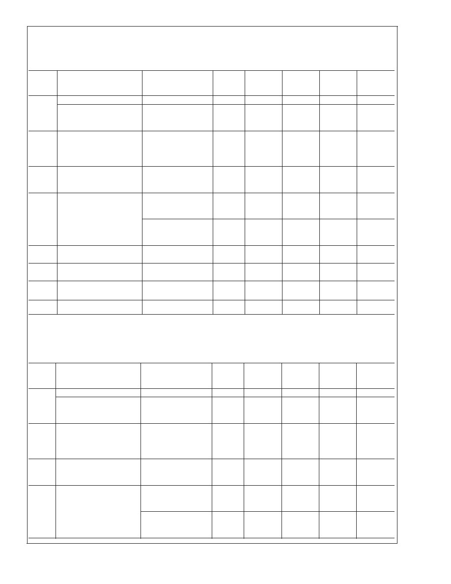
LM4050-4.1
Electrical Characteristics
Boldface limits apply for T
A
= T
J
= T
MIN
to T
MAX
; all other limits T
A
= T
J
= 25∞C. The grades A, B and C designate initial
Reverse Breakdown Voltage tolerances of
±
0.1%,
±
0.2%, and 0.5% respectively.
Symbol
Parameter
Conditions
Typical
(Note 4)
LM4050AIM3
LM4050AEM3
Limits
(Note 5)
LM4050BIM3
LM4050BEM3
Limits
(Note 5)
LM4050CIM3
LM4050CEM3
Limits
(Note 5)
Units
(Limit)
V
R
Reverse Breakdown Voltage
I
R
= 100 µA
4.096
V
Reverse Breakdown Voltage
Tolerance (Note 6)
I
R
= 100 µA
±
4.1
±
8.2
±
21
mV (max)
Industrial Temp. Range
±
18
±
22
±
34
mV (max)
Extended Temp. Range
±
25
±
29
±
41
mV (max)
I
RMIN
Minimum Operating Current
52
µA
68
68
68
µA (max)
Industrial Temp. Range
73
73
73
µA (max)
Extended Temp. Range
78
78
78
µA (max)
V
R
/
T
Average Reverse Breakdown
Voltage Temperature Coefficient
(Note 6)
I
R
= 10 mA
±
30
ppm/∞C
I
R
= 1 mA
±
20
ppm/∞C
I
R
= 100 µA
±
20
±
50
±
50
±
50
ppm/∞C (max)
V
R
/
I
R
Reverse Breakdown Voltage
Change with Operating Current
Change (Note 7)
I
RMIN
I
R
1 mA
0.2
mV
0.9
0.9
0.9
mV (max)
1.2
1.2
1.2
mV (max)
1 mA
I
R
15 mA
2.0
mV
7.0
7.0
7.0
mV (max)
10.0
10.0
10.0
mV (max)
Z
R
Reverse Dynamic Impedance
I
R
= 1 mA, f = 120 Hz,
0.5
I
AC
= 0.1 I
R
e
N
Wideband Noise
I
R
= 100 µA
93
µV
rms
10 Hz
f 10 kHz
V
R
Reverse Breakdown Voltage
Long Term Stability
t = 1000 hrs
T = 25∞C
±
0.1∞C
I
R
= 100 µA
120
ppm
V
HYST
Thermal Hysteresis
(Note 8)
T = -40∞C to 125∞C
1.148
mV
LM4050-5.0
Electrical Characteristics
Boldface limits apply for T
A
= T
J
= T
MIN
to T
MAX
; all other limits T
A
= T
J
= 25∞C. The grades A, B and C designate initial
Reverse Breakdown Voltage tolerances of
±
0.1%,
±
0.2% and 0.5% respectively.
Symbol
Parameter
Conditions
Typical
(Note 4)
LM4050AIM3
LM4050AEM3
Limits
(Note 5)
LM4050BIM3
LM4050BEM3
Limits
(Note 5)
LM4050CIM3
LM4050CEM3
Limits
(Note 5)
Units
(Limit)
V
R
Reverse Breakdown Voltage
I
R
= 100 µA
5.000
V
Reverse Breakdown Voltage
Tolerance (Note 6)
I
R
= 100 µA
±
5.0
±
10
±
25
mV (max)
Industrial Temp. Range
±
22
±
27
±
42
mV (max)
Extended Temp. Range
±
30
±
35
±
50
mV (max)
I
RMIN
Minimum Operating Current
56
µA
74
74
74
µA (max)
Industrial Temp. Range
80
80
80
µA (max)
Extended Temp. Range
90
90
90
µA (max)
V
R
/
T
Average Reverse Breakdown
Voltage Temperature Coefficient
(Note 6)
I
R
= 10 mA
±
30
ppm/∞C
I
R
= 1 mA
±
20
ppm/∞C
I
R
= 100 µA
±
20
±
50
±
50
±
50
ppm/∞C (max)
V
R
/
I
R
Reverse Breakdown Voltage
Change with Operating Current
Change (Note 7)
I
RMIN
I
R
1 mA
0.2
mV
1.0
1.0
1.0
mV (max)
1.4
1.4
1.4
mV (max)
1 mA
I
R
15 mA
2.0
mV
8.0
8.0
8.0
mV (max)
12.0
12.0
12.0
mV (max)
LM4050
www.national.com
5