 | –≠–ª–µ–∫—Ç—Ä–æ–Ω–Ω—ã–π –∫–æ–º–ø–æ–Ω–µ–Ω—Ç: LM4610N | –°–∫–∞—á–∞—Ç—å:  PDF PDF  ZIP ZIP |

LM4610
Dual DC Operated Tone/Volume/Balance Circuit with
National 3-D Sound
General Description
The LM4610 is a DC controlled tone (bass/treble), volume
and balance circuit for stereo applications in car radio, TV
and audio systems. It also features National's 3D-Sound Cir-
cuitry which can be externally adjusted via a simple RC Net-
work. An additional control input allows loudness compensa-
tion to be simply effected.
Four control inputs provide control of the bass, treble, bal-
ance and volume functions through application of DC volt-
ages from a remote control system or, alternatively, from four
potentiometers which may be biased from a zener regulated
supply provided on the circuit.
Each tone response is defined by a single capacitor chosen
to give the desired characteristic.
Features
n
National 3-D Sound
n
Wide supply voltage range, 9V to 16V
n
Large volume control range, 75 dB typical
n
Tone control,
±
15 dB typical
n
Channel separation, 75 dB typical
n
Low distortion, 0.06% typical for an input level of 0.3
Vrms
n
High signal to noise, 80 dB typical for an input level of
0.3 Vrms
n
Few external components required
Block and Connection Diagram
Dual-In-Line Package
DS101125-1
Order Number LM4610N
See NS Package Number N24A
May 1999
LM4610
Dual
DC
Operated
T
one/V
olume/Balance
Circuit
with
National
3-D
Sound
© 1999 National Semiconductor Corporation
DS101125
www.national.com
Absolute Maximum Ratings
(Note 1)
If Military/Aerospace specified devices are required,
please contact the National Semiconductor Sales Office/
Distributors for availability and specifications.
Supply Voltage
16V
Control Pin Voltage (Pins 6, 9, 11, 14,
16)
V
CC
Operating Temperature Range
0∞C to +70∞C
Storage Temperature Range
-65∞C to +150∞C
Power Dissipation
1.5W
Lead Temp. (Soldering, 10 seconds)
260∞C
Note 1: "Absolute Maximum Ratings" indicate limits beyond which damage
to the device may occur. Operating Ratings indicate conditions for which the
device is functional, but do not guarantee specific performance limits.
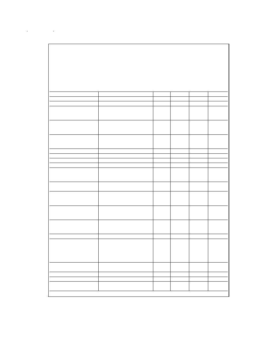
Electrical Characteristics
V
CC
=12V, T
A
=25∞C (unless otherwise stated)
Parameter
Conditions
Min
Typ
Max
Units
Supply Voltage Range
Pin 13
9
16
V
Supply Current
35
45
mA
Zener Regulated Output
Pin 19
Voltage
5.4
V
Current
5
mA
Maximum Output Voltage
Pins 10, 15; f=1 kHz
V
CC
=9V, Maximum Gain
0.8
Vrms
V
CC
=12V
0.8
1.0
Vrms
Maximum Input Voltage
Pins 2, 23; f=1 kHz, V
CC
= 9V
1.3
1.1
Vrms
(Note 2)
Flat Gain Response, V
CC
= 12V
1.6
Vrms
Gain=-10 dB
Input Resistance
Pins 2, 23; f=1 kHz
20
30
k
Output Resistance
Pins 10, 15; f=1 kHz
20
Maximum Gain
V(Pin 14)=V(Pin 19); f=1 kHz
-2
0
2
dB
Volume Control Range
f=1 kHz
70
75
dB
Gain Tracking
f=1 kHz
Channel 1≠Channel 2
0 dB through -40 dB
1
3
dB
-40 dB through -60 dB
2
dB
Balance Control Range
Pins 10, 15; f=1 kHz
1
dB
-26
-20
dB
Bass Control Range
f=40 Hz, C
b
=0.39 µF
(Note 3)
V(Pin 10)=V(Pin 19)
12
15
18
dB
V(Pin 10)=0V
-12
-15
-18
dB
Treble Control Range
f= 16 kHz, C
t
,=0.01 µF
(Note 3)
V(Pin 6)=V(Pin 19)
12
15
18
dB
V(Pin 6)=0V
-12
-15
-18
dB
Total Harmonic Distortion
f=1 kHz, V
IN
=0.3 Vrms
Gain=0 dB
0.06
0.3
%
Gain=-30 dB
0.03
%
Channel Separation
f=1 kHz, Maximum Gain
60
75
dB
Signal/Noise Ratio
Unweighted 100 Hz≠20 kHz
80
dB
Maximum Gain, 0 dB=0.3 Vrms
CCIR/ARM (Note 4)
Gain=0 dB, V
IN
=0.3 Vrms
75
79
dB
Gain=-20 dB, V
IN
=1.0 Vrms
72
dB
Output Noise Voltage at
CCIR/ARM (Note 4)
10
µV
Minimum Gain
Supply Ripple Rejection
200 mVrms, 1 kHz Ripple
35
-50
dB
Control Input Currents
Pins 6, 9, 11, 14, 16(V=0V)
-0.6
-2.5
µA
Frequency Response
-1 dB (Flat Response
250
kHz
20 Hz≠16 kHz)
www.national.com
2
Electrical Characteristics
(Continued)
Note 2: The maximum permissible input level is dependent on tone and volume settings. See Application Notes.
Note 3: The tone control range is defined by capacitors C
b
and C
t
. See Application Notes.
Note 4: Gaussian noise, measured over a period of 50 ms per channel, with a CCIR filter referenced to 2 kHz and an average-responding meter.
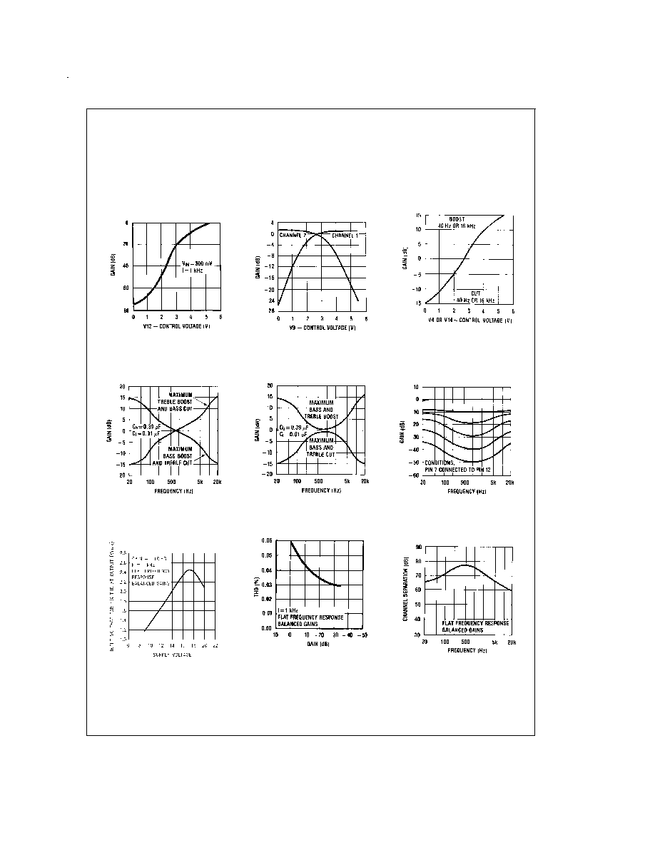
Typical Performance Characteristics
Volume Control
Characteristics
DS101125-20
Balance Control
Characteristic
DS101125-21
Tone Control Characteristic
DS101125-22
Tone Characteristic (Gain
vs Frequency)
DS101125-23
Tone Characteristic (Gain
vs Frequency)
DS101125-24
Loudness Compensated
Volume Characteristic
DS101125-25
Input Signal Handling vs
Supply Voltage
DS101125-33
THD vs Gain
DS101125-27
Channel Separation vs
Frequency
DS101125-28
www.national.com
3
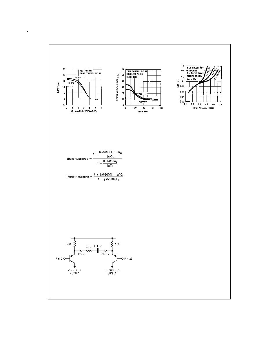
Typical Performance Characteristics
(Continued)
Application Notes
TONE RESPONSE
The maximum boost and cut can be optimized for individual
applications by selection of the appropriate values of C
t
(treble) and C
b
(bass).
The tone responses are defined by the relationships:
Where a
b
=a
t
=0 for maximum bass and treble boost respec-
tively and a
b
=a
t
=1 for maximum cut.
For the values of C
b
and C
t
of 0.39 µF and 0.01 µF as shown
in the Application Circuit, 15 dB of boost or cut is obtained at
40 Hz and 16 kHz.
NATIONAL 3D-SOUND
When stereo speakers need to be closer than optimum be-
cause of equipment /cabinet limitations, an improved stereo
effect can be obtained using a modest amount of phase - re-
versed interchannel cross-coupling. In the LM4610 the input
stage tramsistor emitters are brought out to facillitate this.
The arrangement is shown below in the basic form.
With a monophonic source, the emitters have the same sig-
nal and the resistor and capacitor connected between them
have no effect. With a stereo signal each transistor works in
the grounded base mode for stereo components, generating
an in-phase signal from the opposite channel. As the normal
signals
are
inverted
at
this
point,
the
appropriate
phase-reversed cross-coupling is achieved. An effective
level of coupling of 60% can be obtained using 4.7k in con-
junction with the internal 6.5k emitter resistors. At low fre-
quencies, speakers become less directional and it becomes
desirable to reduce the enhancement effect. With a 0.1µF
coupling capacitor, as shown, roll-off occurs below 330 Hz.
The coupling components may be varied for alternative re-
sponses.
ZENER VOLTAGE
A zener voltage (pin 19=5.4V) is provided which may be
used to bias the control potentiometers. Setting a DC level of
one half of the zener voltage on the control inputs, pins 6,11,
and 16, results in the balanced gain and flat response condi-
tion. Typical spread on the zener voltage is
±
100 mV and
this must be taken into account if control signals are used
which are not referenced to the zener voltage. If this is the
case, then they will need to be derived with similar accuracy.
LOUDNESS COMPENSATION
A simple loudness compensation may be effected by apply-
ing a DC control voltage to pin 9. This operates on the tone
control stages to produce an additional boost limited by the
maximum boost defined by C
b
and C
t
. There is no loudness
compensation when pin 9 is connected to pin 19. Pin 9 can
be connected to pin 14 to give the loudness compensated
volume characteristic as illustrated without the addition of
further external components. (Tone settings are for flat re-
sponse, C
b
and C
t
as given in Application Circuit.) Modifica-
tion to the loudness characteristic is possible by changing
the capacitors C
b
and C
t
for a different basic response or, by
a resistor network between pins 9 and 14 for a different
threshold and slope.
SIGNAL HANDLING
The volume control function of the LM4610 is carried out in
two stages, controlled by the DC voltage on pin 14, to im-
prove signal handling capability and provide a reduction of
output noise level at reduced gain. The first stage is before
the tone control processing and provides an initial 15 dB of
gain reduction, so ensuring that the tone sections are not
overdriven by large input levels when operating with a low
volume setting. Any combination of tone and volume settings
Loudness Control
Characteristic
DS101125-29
Output Noise Voltage
vs Gain
DS101125-30
THD vs Input Voltage
DS101125-31
DS101125-34
www.national.com
4
Application Notes
(Continued)
may be used provided the output level does not exceed
1 Vrms, V
CC
=12V (0.7 Vrms, V
CC
=9V). At reduced gain
(
<
-6 dB)the input stage will overload if the input level ex-
ceeds 1.6 Vrms, V
CC
=12V (1.1 Vrms, V
CC
=9V). As there is
volume control on the input stages, the inputs may be oper-
ated with a lower overload margin than would otherwise be
acceptable, allowing a possible improvement in signal to
noise ratio.
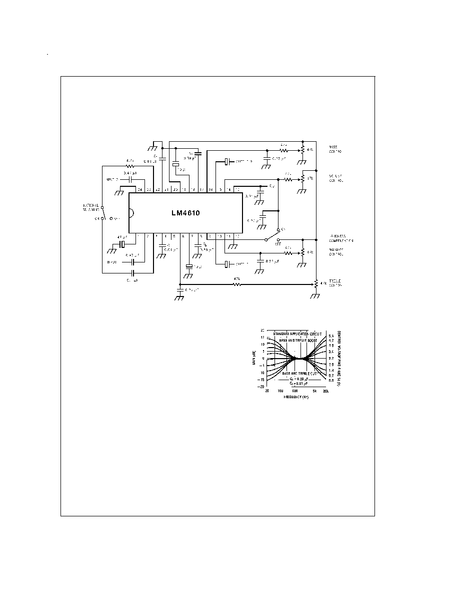
Application Circuit
Applications Information
OBTAINING MODIFIED RESPONSE CURVES
The LM4610 is a dual DC controlled bass, treble, balance
and volume integrated circuit ideal for stereo audio systems.
In the various applications where the LM4610 can be used,
there may be requirements for responses different to those
of the standard application circuit given in the data sheet.
This application section details some of the simple variations
possible on the standard responses, to assist the choice of
optimum characteristics for particular applications.
TONE CONTROLS
Summarizing the relationship given in the data sheet, basi-
cally for an increase in the treble control range C
t
must be in-
creased, and for increased bass range C
b
must be reduced.
Figure 1 shows the typical tone response obtained in the
standard application circuit. (C
t
=0.01 µF, C
b
=0.39 µF). Re-
sponse curves are given for various amounts of boost and
cut.
Figure 2 and Figure 3 show the effect of changing the re-
sponse defining capacitors C
t
and C
b
to 2Ct, C
b
/2 and 4C
t
,
C
b
/4 respectively, giving increased tone control ranges. The
values of the bypass capacitors may become significant and
affect the lower frequencies in the bass response curves.
DS101125-35
DS101125-4
FIGURE 1. Tone Characteristic (Gain vs Frequency)
www.national.com
5