LM4842
Stereo 2W Amplifiers with DC Volume Control,
Transient Free Outputs, and Cap-less Headphone Drive
General Description
The LM4842 is a monolithic integrated circuit that provides
DC volume control, and stereo bridged audio power amplifi-
ers capable of producing 2W into 4
(Note 1) or 2.2W into
3
(Note 2) with less than 1.0% THD+N.
Boomer
Æ
audio integrated circuits were designed specifically
to provide high quality audio while requiring a minimum
amount of external components. The LM4842 incorporates a
DC volume control, stereo bridged audio power amplifiers,
new cap-less headphone driver circuit (patent pending), se-
lectable gain or bass boost, and an input mux making it
optimally suited for multimedia monitors, portable radios,
desktop, and portable computer applications.
The LM4842 features an externally controlled, low-power
consumption shutdown mode (Shutdown Low), and both a
power amplifier and headphone mute for maximum system
flexibility and performance.
Note 1: When properly mounted to the circuit board, the LM4842MH will
deliver 2W into 4
. The LM4842MT will deliver 1.1W into 8. See the
Application Information section for LM4842MH usage information.
Note 2: An LM4842MH that has been properly mounted to the circuit board
and forced-air cooled will deliver 2.2W into 3
.
Key Specifications
n
P
O
at 1% THD+N
n
into 3
(MH and LQ)
2.2W(typ)
n
into 4
(MH and LQ)
2.0W(typ)
n
into 8
(MT, MH, and LQ)
1.1W(typ)
n
Single-ended THD+N at 85mW into 32
1.0%(typ)
n
Shutdown current (Shutdown Low)
0.2µA(typ)
Features
n
Stereo headphone amplifier mode that eliminates the
Output Coupling Capacitors (patent pending)
n
Advanced "click and pop" suppression circuitry
n
Acoustically Enhanced DC Volume Control Taper
n
2 Channel Stereo Input MUX
n
System Beep Detect
n
Stereo switchable bridged/single-ended power amplifiers
n
Selectable internal/external gain and bass boost
n
Thermal shutdown protection circuitry
Applications
n
Portable and Desktop Computers
n
Multimedia Monitors
n
Portable Radios, PDAs, and Portable TVs
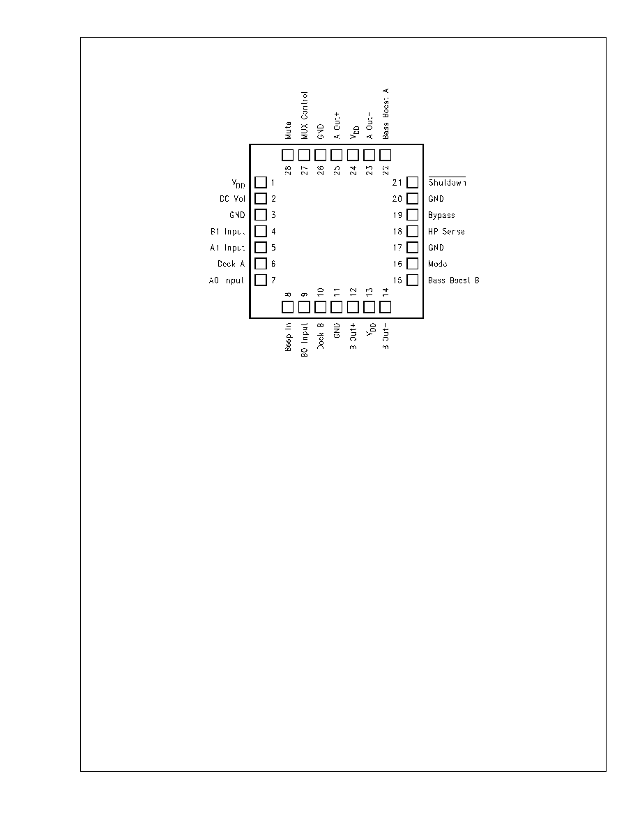
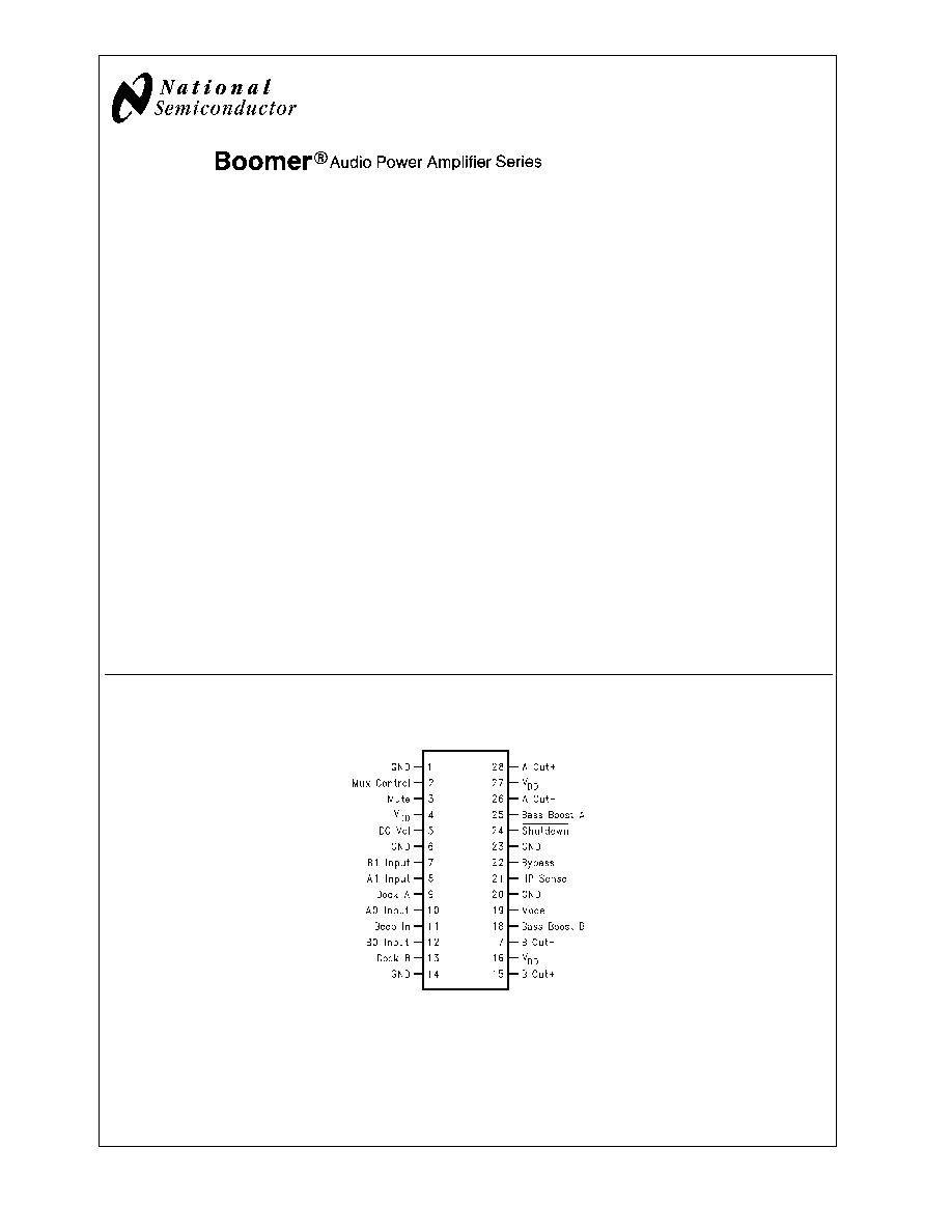
Connection Diagrams
TSSOP Package
20028102
Top View
Order Number LM4842MT
See NS Package Number MTC28 for TSSOP
Order Number LM4842MH
See NS Package Number MXA28A for Exposed-DAP TSSOP
Boomer
Æ
is a registered trademark of NationalSemiconductor Corporation.
September 2002
LM4842
Stereo
2W
Amplifiers
with
DC
V
olume
Control,
T
ransient
Free
Outputs,
and
Cap-less
Headphone
Drive
© 2002 National Semiconductor Corporation
DS200281
www.national.com
Absolute Maximum Ratings
(Note 10)
If Military/Aerospace specified devices are required,
please contact the National Semiconductor Sales Office/
Distributors for availability and specifications.
Supply Voltage
6.0V
Storage Temperature
-65∞C to +150∞C
Input Voltage
-0.3V to V
DD
+0.3V
Power Dissipation (Note 11)
Internally limited
ESD Susceptibility (Note 12)
All pins except Pin 28
2500V
Pin 28
6500V
ESD Susceptibility (Note 13)
200V
Junction Temperature
150∞C
Soldering Information
Vapor Phase (60 sec.)
215∞C
Infrared (15 sec.)
220∞C
See AN-450 "Surface Mounting and their Effects on
Product Reliability" for other methods of soldering surface
mount devices.
JC
(typ) -- LQA028A
3∞C/W
JA
(typ) -- LQA028A
42∞C/W
JC
(typ) -- MTC28
20∞C/W
JA
(typ) -- MTC28
80∞C/W
JC
(typ) -- MXA28A
2∞C/W
JA
(typ) -- MXA28A (exposed
DAP) (Note 4)
41∞C/W
JA
(typ) -- MXA28A (exposed
DAP) (Note 3)
54∞C/W
JA
(typ) -- MXA28A (exposed
DAP) (Note 5)
59∞C/W
JA
(typ) -- MXA28A (exposed
DAP) (Note 6)
93∞C/W
Operating Ratings
Temperature Range
T
MIN
T
A
T
MAX
-40∞C
TA 85∞C
Supply Voltage
2.7V
V
DD
5.5V
Electrical Characteristics for Entire IC
(Notes 7, 10)
The following specifications apply for V
DD
= 5V and T
A
= 25∞C unless otherwise noted.
Symbol
Parameter
Conditions
LM4842
Units
(Limits)
Typical
(Note 14)
Limit
(Note 15)
V
DD
Supply Voltage
2.7
V (min)
5.5
V (max)
I
DD
Quiescent Power Supply Current
V
IN
= 0V, I
O
= 0A
15
30
mA (max)
I
SD
Shutdown Current
V
Shutdown
= GND
0.7
2.0
µA (max)
V
IH
VIN High on all Logic Inputs
0.8 x V
DD
V (min)
V
IL
VIN Low on all Logic Inputs
0.2 x V
DD
V (max)
TH
um
Un-Mute Threshold Voltage
V
Shutdown
= V
DD
,
Gain 1st Stage = 1
22
10
40
mV
RMS
mV
RMS
Electrical Characteristics for Volume Attenuators
(Notes 7, 10)
The following specifications apply for V
DD
= 5V and T
A
= 25∞C unless otherwise noted.
Symbol
Parameter
Conditions
LM4842
Units
(Limits)
Typical
(Note 14)
Limit
(Note 15)
C
RANGE
Attenuator Range
Gain with V
DCVol
= 5.0V, No Load
±
0.75
dB (max)
C
RANGE
Attenuator Range
Attenuation with V
DCVol
= 0V (BM &
SE)
-75
dB (min)
A
M
Mute Attenuation
V
mute
= 5V, Bridged Mode (BM)
-78
dB (min)
V
mute
= 5V, Single-Ended Mode (SE)
-78
dB (min)
Electrical Characteristics for Single-Ended Mode Operation
(Notes 7, 10)
The following specifications apply for V
DD
= 5V and T
A
= 25∞C unless otherwise noted.
Symbol
Parameter
Conditions
LM4842
Units
(Limits)
Typical
(Note 14)
Limit
(Note 15)
P
O
Output Power
THD+N = 1.0%; f = 1kHz; R
L
= 32
85
mW
THD+N = 10%; f = 1 kHz; R
L
= 32
95
mW
LM4842
www.national.com
4
Electrical Characteristics for Single-Ended Mode Operation
(Notes 7,
10) (Continued)
The following specifications apply for V
DD
= 5V and T
A
= 25∞C unless otherwise noted.
Symbol
Parameter
Conditions
LM4842
Units
(Limits)
Typical
(Note 14)
Limit
(Note 15)
THD+N
Total Harmonic Distortion+Noise
V
OUT
= 1V
RMS
, f=1kHz, R
L
= 10k
,
A
VD
= 1
0.065
%
PSRR
Power Supply Rejection Ratio
C
B
= 1.0 µF, f =120 Hz,
V
RIPPLE
= 200 mVrms
58
dB
SNR
Signal to Noise Ratio
P
OUT
=75 mW, R
L
= 32
, A-Wtd
Filter
102
dB
X
talk
Channel Separation
f=1kHz, C
B
= 1.0 µF
65
dB
Electrical Characteristics for Bridged Mode Operation
(Notes 7, 10)
The following specifications apply for V
DD
= 5V and T
A
= 25∞C unless otherwise noted.
Symbol
Parameter
Conditions
LM4842
Units
(Limits)
Typical
(Note 14)
Limit
(Note 15)
V
OS
Output Offset Voltage
V
IN
= 0V, No Load
5
±
50
mV (max)
P
O
Output Power
THD + N = 1.0%; f=1kHz; R
L
= 3
(Note 8)
2.2
W
THD + N = 1.0%; f=1kHz; R
L
= 4
(Note 9)
2
W
THD = 1.0% (max);f = 1 kHz;
R
L
= 8
1.1
1.0
W (min)
THD+N = 10%;f = 1 kHz; R
L
= 8
1.5
W
THD+N
Total Harmonic Distortion+Noise
P
O
= 1W, 20 Hz
<
f
<
20 kHz,
R
L
= 8
, A
VD
= 2
0.3
%
P
O
= 340 mW, R
L
= 32
1.0
%
PSRR
Power Supply Rejection Ratio
C
B
= 1.0 µF, f = 120 Hz,
V
RIPPLE
= 200 mVrms; R
L
= 8
74
dB
SNR
Signal to Noise Ratio
V
DD
= 5V, P
OUT
= 1.1W, R
L
= 8
,
A-Wtd Filter
93
dB
X
talk
Channel Separation
f=1kHz, C
B
= 1.0 µF
70
dB
LM4842
www.national.com
5