 | –≠–ª–µ–∫—Ç—Ä–æ–Ω–Ω—ã–π –∫–æ–º–ø–æ–Ω–µ–Ω—Ç: LM4844TLX | –°–∫–∞—á–∞—Ç—å:  PDF PDF  ZIP ZIP |
LM4844
Stereo 1.2W Audio Sub-system with 3D Enhancement
General Description
The LM4844 is an integrated audio sub-system designed for
stereo cell phone applications. Operating on a 3.3V supply, it
combines a stereo speaker amplifier delivering 495mW per
channel into an 8
load and a stereo OCL headphone
amplifier delivering 33mW per channel into a 32
load.
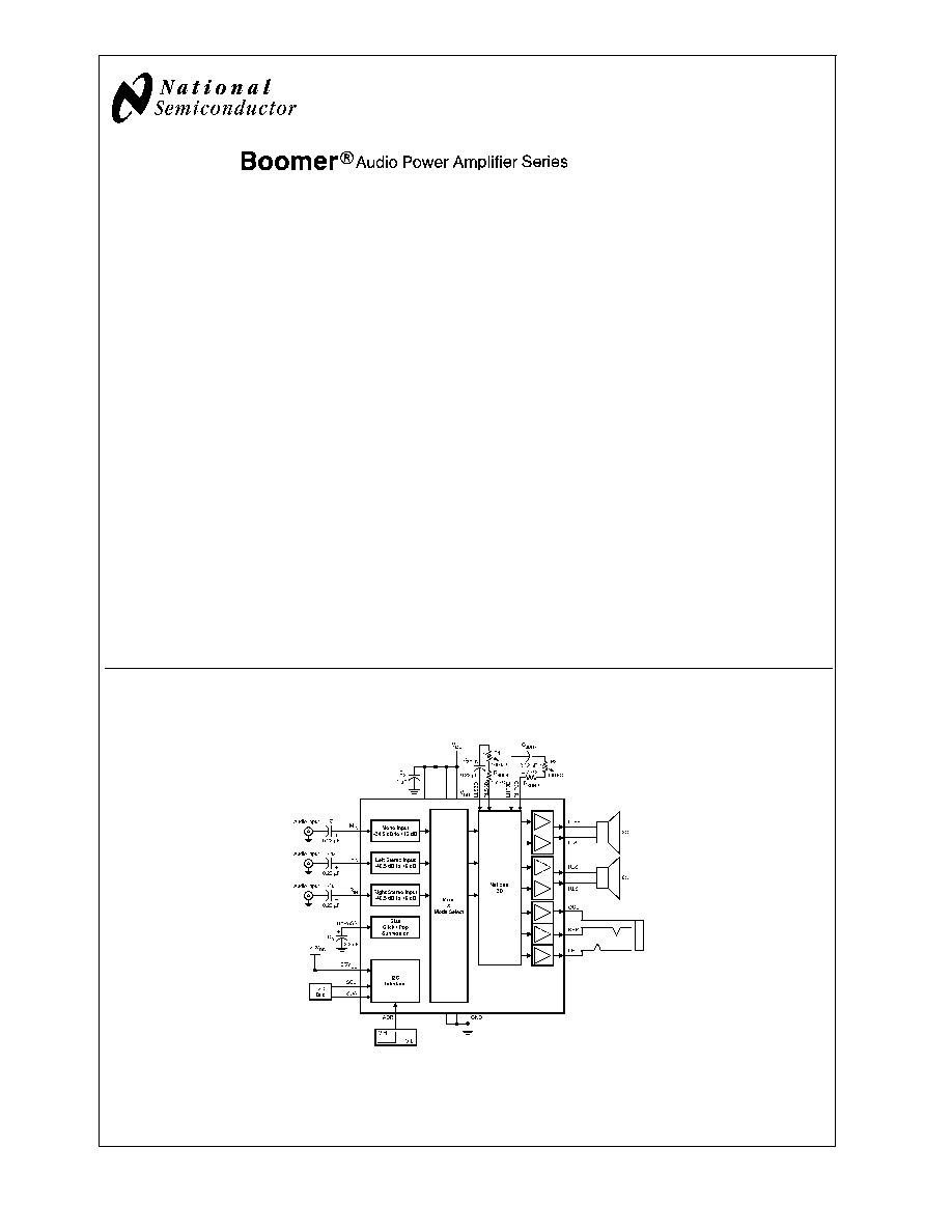
It integrates the audio amplifiers, volume control, mixer,
power management control, and National 3D enhancement
all into a single package. In addition, the LM4844 routes and
mixes the stereo and mono inputs into 10 distinct output
modes. The LM4844 is controlled through an I
2
C compatible
interface.
Boomer audio power amplifiers are designed specifically to
provide high quality output power with a minimal amount of
external components.
The LM4844 is available in a very small 2.5mm x 2.9mm
30-bump micro SMD (TL) package.
Key Specifications
j
P
OUT
, Stereo BTL, 8
, 3.3V,
1% THD+N
495mW (typ)
j
P
OUT
HP, 32
, 3.3V,
1% THD+N
33mW (typ)
j
Shutdown Current, 3.3V
0.1µA (typ)
Features
n
Stereo speaker amplifier
n
Stereo OCL headphone amplifier
n
Independent Left, Right, and Mono volume controls
n
National 3D enhancement
n
I
2
C compatible interface
n
Ultra low shutdown current
n
Click and Pop Suppression circuit
n
10 distinct output modes
Applications
n
Cell Phones
n
PDAs
n
Portable Gaming Devices
n
Internet Appliances
n
Portable DVD, CD, AAC, and MP3 Players
Block Diagram
Boomer
Æ
is a registered trademark of National Semiconductor Corporation.
20153531
FIGURE 1. Audio Sub-system Block Diagram
June 2005
LM4844
Stereo
1.2W
Audio
Sub-system
with
3D
Enhancement
© 2005 National Semiconductor Corporation
DS201535
www.national.com
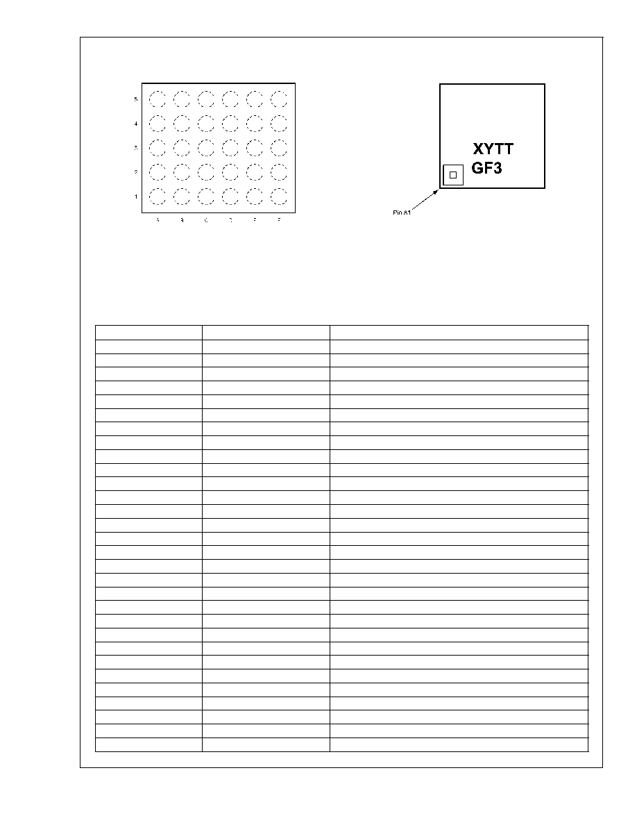
Connection Diagrams
30 Bump Micro SMD (TL) Package
Micro SMD (TL) Marking
20153508
Top View
(Bump-side down)
Order Number LM4844TL
See NS Package Number TLA30CZA
20153592
Top View
XY = 2 Digit Date Code
TT = Die Traceability
G = Boomer Family
F3 = LM4844TL
Pin Connection (TL)
Pin
Name
Pin Description
A1
RLS+
Right Loudspeaker Positive Output
A2
V
DD
Power Supply
A3
SDA
Data
A4
RHP3D
Right Headphone 3D
A5
RHP
Right Headphone Output
B1
GND
Ground
B2
I
2
CV
DD
I
2
C Interface Power Supply
B3
ADR
I
2
C Address Select
B4
LHP3D
Left Headphone 3D
B5
V
DD
Power Supply
C1
RLS-
Right Loudspeaker Negative Output
C2
NC
No Connect
C3
SCL
Clock
C4
NC
No Connect
C5
GND
Ground
D1
LLS-
Left Loudspeaker Negative Output
D2
V
DD
Power Supply
D3
M
IN
Mono Input
D4
NC
No Connect
D5
OCL
V
DD
/2 Supply for headphone jack's sleeve
E1
GND
Ground
E2
BYPASS
Half-supply bypass
E3
LLS3D
Left Loudspeaker 3D
E4
R
IN
Right Stereo Input
E5
NC
No Connect
F1
LLS+
Left Loudspeaker Positive Output
F2
V
DD
Power Supply
F3
RLS3D
Right Loudspeaker 3D
F4
L
IN
Left Stereo Input
F5
LHP
Left Headphone Output
LM4844
www.national.com
2
Absolute Maximum Ratings
(Notes 1, 2)
If Military/Aerospace specified devices are required,
please contact the National Semiconductor Sales Office/
Distributors for availability and specifications.
Supply Voltage
6.0V
Storage Temperature
-65∞C to +150∞C
Input Voltage
-0.3V to V
DD
+0.3V
Power Dissipation (Note 3)
Internally Limited
ESD Susceptibility (Note 4)
2000V
ESD Susceptibility (Note 5)
200V
Junction Temperature (T
J
)
150∞C
Thermal Resistance
JA
(TLA30CZA)
62∞C/W
Operating Ratings
Temperature Range
T
MIN
T
A
T
MAX
-40∞C
T
A
+85∞C
Supply Voltage
2.7V
V
DD
5.5V
≠2.5V
I
2
CV
DD
5.5V
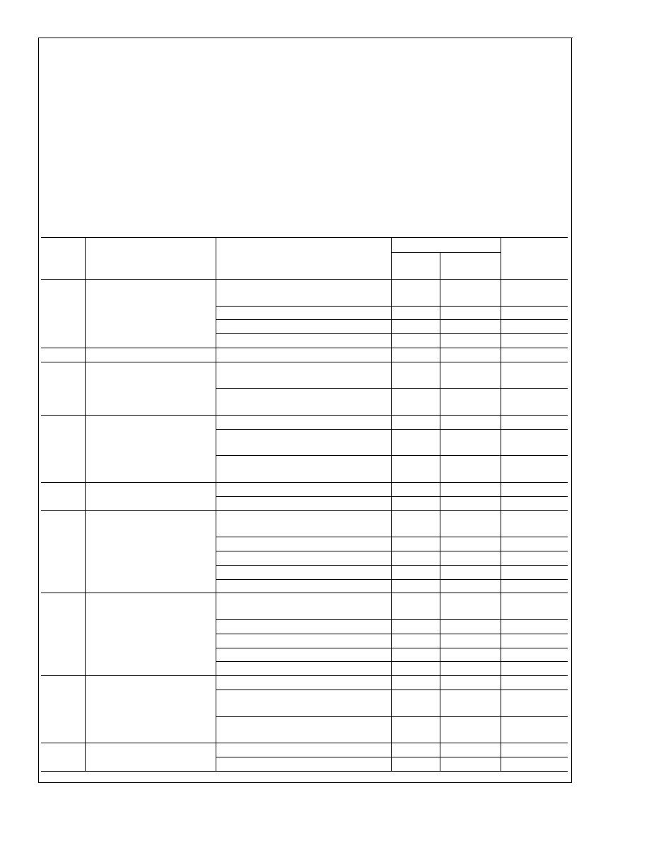
Audio Amplifier Electrical Characteristics V
DD
= 5.0V
(Notes 1, 2)
The following specifications apply for V
DD
= 5.0V, unless otherwise specified. Limits apply for T
A
= 25∞C.
Symbol
Parameter
Conditions
LM4844
Units
(Limits)
Typical
(Note 6)
Limits (Notes
7, 8)
I
DD
Supply Current
V
IN
= 0V, No load;
LD5 = RD5 = 0
Mode 4, 9, 14
5
8
mA (max)
Mode 2, 7, 12
12
18
mA (max)
Mode 3, 8, 13
13
20
mA (max)
I
SD
Shutdown Current
Mode 0
0.2
2.5
µA (max)
P
O
Output Power
Speaker; THD+N = 1%;
f = 1kHz; 8
BTL
1.2
0.9
W (min)
Headphone; THD+N = 1%;
f = 1kHz; 32
SE
80
60
mW (min)
THD+N
Total Harmonic Distortion Plus
Noise
LD5 = RD5 = 0
Speaker; P
O
= 400mW;
f = 1kHz; 8
BTL
0.05
%
Headphone; P
O
= 15mW;
f = 1kHz; 32
SE
0.06
%
V
OS
Offset Voltage
Speaker; LD5 = RD5 = 0
5
40
mV (max)
Headphone; LD5 = RD5 = 0
2
30
mV (max)
N
OUT
Output Noise
A-weighted, 0dB gain;
LD5 = RD5 = 0
Speaker; Mode 2, 3, 7, 8
31
µV
Speaker; Mode 12, 13
35
µV
Headphone; Mode 3, 4, 8, 9
12
µV
Headphone; Mode 13, 14
14
µV
PSRR
Power Supply Rejection Ratio
f = 217Hz; V
rip
= 200mV
pp
; C
B
= 2.2µF;
0dB Gain Setting; LD5 = RD5 = 0
Speaker; Mode 2, 3, 7, 8
71
dB
Speaker; Mode 12, 13,
65
55
dB (min)
Headphone; Mode 3, 4, 8, 9
76
dB
Headphone; Mode 13, 14
72
62
dB (min)
Xtalk
Crosstalk
LD5 = RD5 = 0
Loudspeaker; P
O
= 400mW;
f = 1kHz
84
dB
Headphone; P
O
= 15mW;
f = 1kHz
60
dB
T
WU
Wake-up Time
CD4 = 0; C
B
= 2.2µF
103
ms
CD4 = 1; C
B
= 2.2µF
42
ms
LM4844
www.national.com
3
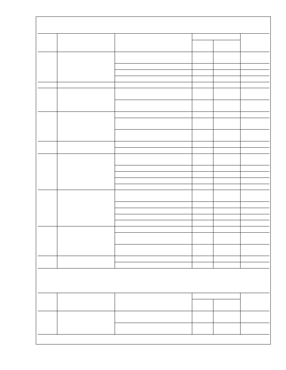
Audio Amplifier Electrical Characteristics V
DD
= 3.0V
(Notes 1, 2)
The following specifications apply for V
DD
= 3.0V, unless otherwise specified. Limits apply for T
A
= 25∞C.
Symbol
Parameter
Conditions
LM4844
Units
(Limits)
Typical
(Note 6)
Limits (Notes
7, 8)
I
DD
Supply Current
V
IN
= 0V, No load;
LD5 = RD5 = 0
Mode 4, 9, 14
4.5
7.5
mA (max)
Mode 2, 7, 12
10
16
mA (max)
Mode 3, 8, 13
11
18
mA (max)
I
SD
Shutdown Current
Mode 0
0.1
2
µA (max)
P
O
Output Power
Speaker; THD+N = 1%;
f = 1kHz; 4
BTL
390
320
mW (min)
Headphone; THD+N = 1%;
f = 1kHz; 32
SE
28
21
mW (min)
THD+N
Total Harmonic Distortion Plus
Noise
LD5 = RD5 = 0
Speaker; P
O
= 200mW;
f = 1kHz; 8
BTL
0.05
%
Headphone; P
O
= 10mW;
f = 1kHz; 32
SE
0.05
%
V
OS
Offset Voltage
Speaker; LD5 = RD5 = 0
5
40
mV (max)
Headphone; LD5 = RD5 = 0
2
30
mV (max)
N
OUT
Output Noise
A-weighted; 0dB gain;
LD5 = RD5 = 0
Speaker; Mode 2, 3, 7, 8
32
µV
Speaker; Mode 12, 13
41
µV
Headphone; Mode 3, 4, 8, 9
13
µV
Headphone; Mode 13, 14
15
µV
PSRR
Power Supply Rejection Ratio
f = 217Hz, V
rip
= 200mV
pp
; C
B
= 2.2µF;
0dB Gain Setting; LD5 = RD5 = 0
Speaker; Mode 2, 3, 7, 8
73
dB
Speaker; Mode 12, 13,
66
55
dB (min)
Headphone; Mode 3, 4, 8, 9
78
dB
Headphone; Mode 13, 14
72
62
dB (min)
Xtalk
Crosstalk
LD5 = RD5 = 0
Loudspeaker; P
O
= 200mW;
f = 1kHz
85
dB
Headphone; P
O
= 10mW;
f = 1kHz
60
dB
T
WU
Wake-up Time
CD4 = 0; C
B
= 2.2µF
70
ms
CD4 = 1; C
B
= 2.2µF
30
ms
Volume Control Electrical Characteristics
(Notes 1, 2)
The following specifications apply for 3V
V
DD
5V and 3V I
2
CV
DD
5V, unless otherwise specified. Limits apply for T
A
=
25∞C.
Symbol
Parameter
Conditions
LM4844
Units
(Limits)
Typical
(Note 6)
Limits (Notes
7, 8)
Stereo Volume Control Range
maximum gain setting
6
5.5
6.5
dB (min)
dB (max)
minimum gain setting
-40.5
-41
-40
dB (min)
dB (max)
LM4844
www.national.com
4

Volume Control Electrical Characteristics
(Notes 1, 2) (Continued)
The following specifications apply for 3V
V
DD
5V and 3V I
2
CV
DD
5V, unless otherwise specified. Limits apply for T
A
=
25∞C.
Symbol
Parameter
Conditions
LM4844
Units
(Limits)
Typical
(Note 6)
Limits (Notes
7, 8)
Mono Volume Control Range
maximum gain setting
12
11.5
12.5
dB (min)
dB (max)
minimum gain setting
-34.5
-35
-34
dB (min)
dB (max)
Volume Control Step Size
1.5
dB
Volume Control Step Size
Error
+/-0.2
+/-0.5
dB (max)
Stereo Channel to Channel
Gain Mismatch
0.3
dB
Mute Attenuation
Mode 12, V
in
= 1V
RMS
Headphone
100
dB
L
IN
and R
IN
Input Impedance
maximum gain setting
33
25
42
k
(min)
k
(max)
minimum gain setting
100
75
125
k
(min)
k
(max)
M
IN
Input Impedance
maximum gain setting
20
15
25
k
(min)
k
(max)
minimum gain setting
96
73
123
k
(min)
k
(max)
Control Interface Electrical Characteristics
(Notes 1, 2)
The following specifications apply for 3V
V
DD
5V and 3V I
2
CV
DD
5V, unless otherwise specified. Limits apply for T
A
=
25∞C.
Symbol
Parameter
Conditions
LM4844
Units
(Limits)
Typical
(Note 6)
Limits (Notes
7, 8)
t
1
SCL period
2.5
µs (min)
t
2
SDA Set-up Time
100
ns (min)
t
3
SDA Stable Time
0
ns (min)
t
4
Start Condition Time
100
ns (min)
t
5
Stop Condition time
100
ns (min)
V
IH
Digital Input High Voltage
0.7 x I
2
CVDD
V (min)
V
IL
Digital Input Low Voltage
0.3 x I
2
CV
DD
V (max)
Note 1: All voltages are measured with respect to the GND pin unless otherwise specified.
Note 2: Absolute Maximum Ratings indicate limits beyond which damage to the device may occur. Operating Ratings indicate conditions for which the device is
functional but do not guarantee specific performance limits. Electrical Characteristics state DC and AC electrical specifications under particular test conditions which
guarantee specific performance limits. This assumes that the device is within the Operating Ratings. Specifications are not guaranteed for parameters where no limit
is given, however, the typical value is a good indication of device performance.
Note 3: The maximum power dissipation must be derated at elevated temperatures and is dictated by T
JMAX
,
JA
, and the ambient temperature, T
A
. The maximum
allowable power dissipation is P
DMAX
= (T
JMAX
- T
A
) /
JA
or the number given in Absolute Maximum Ratings, whichever is lower. For the LM4844 typical application
with V
DD
= 3.3V and R
L
= 8
stereo operation, the total power dissipation is TBDW.
JA
= TBD∞C/W.
Note 4: Human body model, 100pF discharged through a 1.5k
resistor.
Note 5: Machine Model, 220pF-240pF discharged through all pins.
Note 6: Typicals are measured at +25∞C and represent the parametric norm.
Note 7: Limits are guaranteed to National's AOQL (Average Outgoing Quality Level).
Note 8: Datasheet min/max specification limits are guaranteed by design, test, or statistical analysis.
Note 9: Shutdown current and supply current are measured in a normal room environment.
LM4844
www.national.com
5