 | ÐлекÑÑоннÑй компоненÑ: LM73CIMKX | СкаÑаÑÑ:  PDF PDF  ZIP ZIP |
Äîêóìåíòàöèÿ è îïèñàíèÿ www.docs.chipfind.ru
LM73
2.7V, SOT-23, 11-to-14 Bit Digital Temperature Sensor
with 2-Wire Interface
General Description
The LM73 is an integrated, digital-output temperature sensor
featuring an incremental Delta-Sigma ADC with a two-wire
interface that is compatible with the SMBus and I
2
C
®
inter-
faces. The host can query the LM73 at any time to read
temperature. Available in a 6-pin SOT-23 package, the LM73
occupies very little board area while operating over a wide
temperature range (-40°C to 150°C) and providing
±
1.0°C
accuracy from -10°C to 80°C. The user can optimize be-
tween the conversion time and the sensitivity of the LM73 by
programming it to report temperature in any of four different
resolutions. Defaulting to 11-bit mode (0.25°C/LSB), the
LM73 measures temperature in a maximum time of 14 ms,
making it ideal for applications that require temperature data
very soon after power-up. In its maximum resolution, 14-bit
mode (0.03125°C/LSB), the LM73 is optimized to sense very
small changes in temperature.
A single multi-level address line selects one of three unique
device addresses. An open-drain ALERT output goes active
when the temperature exceeds a programmable limit. Both
the data and clock lines are filtered for excellent noise toler-
ance and reliable communication. Additionally, a time-out
feature on the clock and data lines causes the LM73 to
automatically reset these lines if either is held low for an
extended time, thus exiting any bus lock-up condition without
processor intervention.
Applications
n
Portable Electronics
n
Notebook Computers
n
Automotive
n
System Thermal Management
n
Office Electronics
Key Specifications
j
Supply Voltage
2.7V to 5.5V
j
Supply Current
operating
320 µA (typ)
495 µA (max)
shutdown
8 µA (max)
1.9 µA (typ)
j
Temperature
-10°C to 80°C
±
1.0°C (max)
Accuracy
-25°C to 115°C
±
1.5°C (max)
-40°C to 150°C
±
2.0°C (max)
j
Resolution
0.25°C to
0.03125°C
j
Conversion Time
11-bit (0.25°C)
14 ms (max)
14-bit (0.03125°C)
112 ms (max)
Features
n
Single address pin offers choice of three selectable
addresses per version for a total of six possible
addresses.
n
SMBus and I
2
C-compatible two-wire interface
n
Supports 400 kHz operation
n
Shutdown mode with one-shot feature available for very
low average power consumption
n
Programmable digital temperature resolution from 11
bits to 14 bits.
n
Fast conversion rate ideal for quick power up and
measuring rapidly changing temperature
n
Open-drain ALERT output pin goes active when
temperature is above a programmed temperature limit
n
Very stable, low-noise digital ouput.
Typical Application
20147803
I2C is a registered trademark of Philips Electronics N.V. Corporation
October 2005
LM73
2.7V
,
SOT
-23,
1
1-to-14
Bit
Digital
T
emperature
Sensor
with
2-W
ire
Interface
© 2005 National Semiconductor Corporation
DS201478
www.national.com
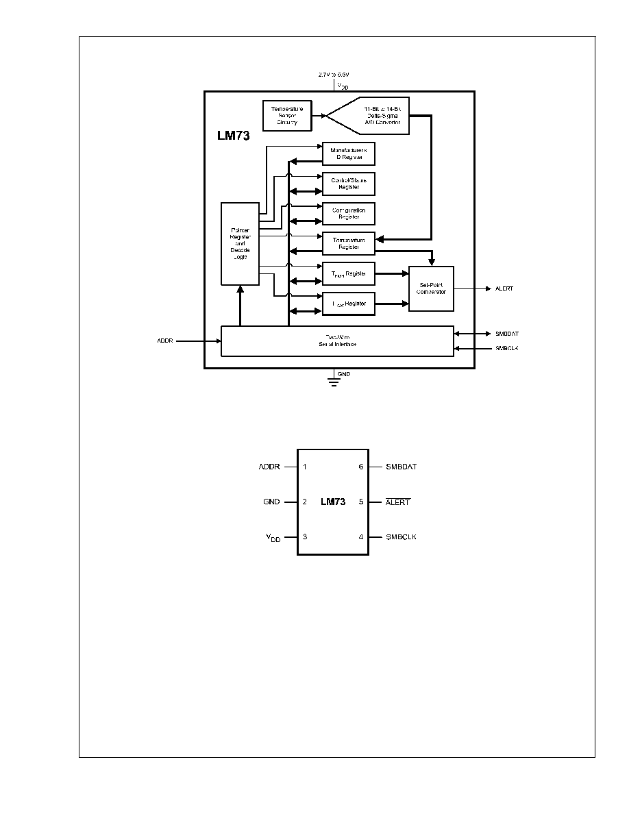
Simplified Block Diagram
20147801
Connection Diagram
SOT23-6
20147802
TOP VIEW
LM73
www.national.com
2
Ordering Information
Part Number
Package
Marking
NS Package
Number
Transport
Media
SMBus Device Address
Address Pin
Device Address
LM73CIMK-0
T730
MK06A
(Thin SOT23-6)
3000 Units on
Tape and Reel
Float
Ground
V
DD
1001 000
1001 001
1001 010
LM73CIMKX-0
T730
MK06A
(Thin SOT23-6)
9000 Units on
Tape and Reel
Float
Ground
V
DD
1001 000
1001 001
1001 010
Note 1: Available in RoHS-compliant packages. More details at www.national.com.
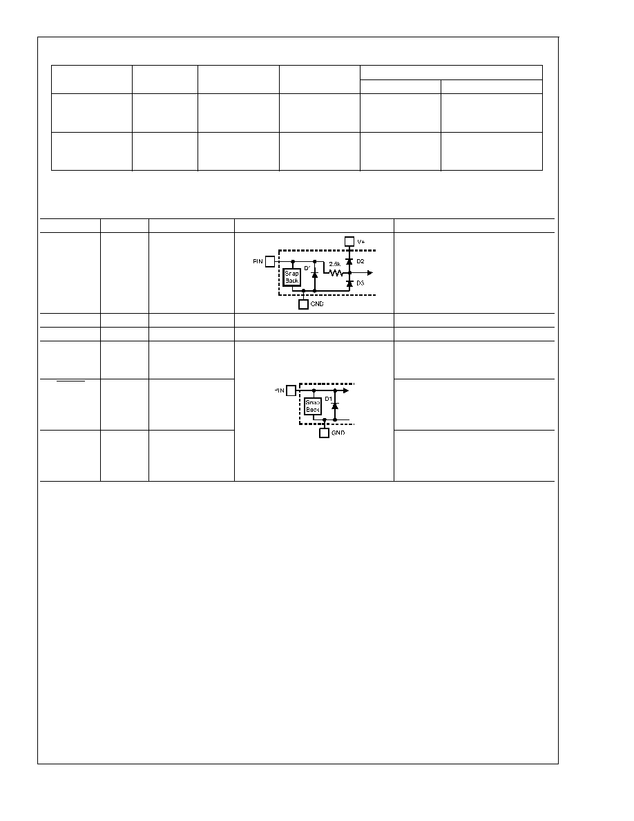
Pin Descriptions
Label
Pin #
Type
Equivalent Circuit
Function
ADDR
1
Logic Input, three
levels
Address Select Input: One of three
device addresses is selected by
connecting to ground, left floating, or
connecting to V
DD
.
GND
2
Ground
Ground
V
DD
3
Power
Supply Voltage
SMBCLK
4
CMOS Logic
Input
Serial Clock: SMBus clock signal.
Operates up to 400 kHz. Low-pass
filtered.
ALERT
5
Open-Drain
Output
Digital output which goes active
whenever the measured temperature
exceeds a programmable
temperature limit.
SMBDAT
6
Open-Drain
Input/Output
Serial Data: SMBus bi-directional
data signal used to transfer serial
data synchronous to the SMBCLK.
Low-pass filtered.
LM73
www.national.com
3
Absolute Maximum Ratings
(Note 2)
Supply Voltage
-0.3 V to 6.0 V
Voltage at Any Pin
-0.3 V to (V
DD
+ 0.5 V)
Input Current at Any Pin (Note 3)
±
5 mA
Storage Temperature
-65°C to +150°C
ESD Susceptibility (Note 5)
Human Body Model
2000 V
Machine Model
200 V
Soldering process must comply with National
Semiconductor's Reflow Temperature Profile
specifications. Refer to www.national.com/packaging.
(Note 4)
Operating Ratings
(Note 2)
Specified Temperature Range
T
MIN
T
A
T
MAX
-40°C
T
A
+150°C
Supply Voltage Range (V
DD
)
+2.7V to +5.5V
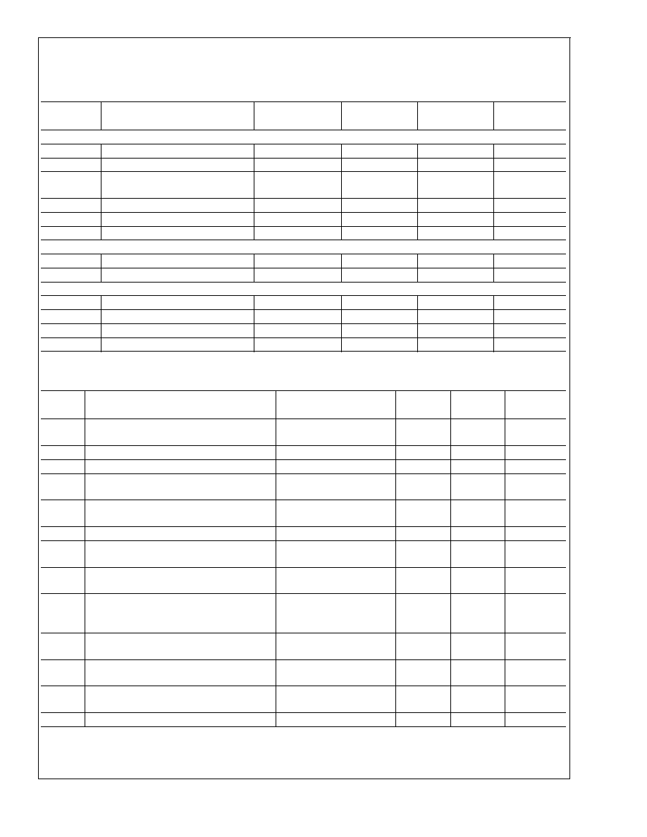
Temperature-to-Digital Converter Characteristics
Unless otherwise noted, these specifications apply for V
DD
= 2.7V to 5.5V. Boldface limits apply for T
A
= T
J
=T
MIN
to T
MAX
;
all other limits T
A
= T
J
= +25°C, unless otherwise noted. T
A
is the ambient temperature. T
J
is the junction temperature.
Parameter
Conditions
Typical
Limits
Units
(Note 6)
(Note 7)
(Limit)
Accuracy (Note 8)
V
DD
= 2.7V to
V
DD
= 4.5V
T
A
= -10°C to 80°C
±
1.0
°C (max)
T
A
= -25°C to 115°C
±
1.5
°C (max)
T
A
= -40°C to 150°C
±
2.0
°C (max)
V
DD
>
4.5V to
V
DD
= 5.5V
T
A
= -10°C to 80°C
±
1.5
°C (max)
T
A
= -25°C to 115°C
±
2.0
°C (max)
T
A
= -40°C to 150°C
±
2.5
°C (max)
Resolution
RES1 Bit = 0, RES0 Bit = 0
11
Bits
0.25
°C/LSB
RES1 Bit = 0, RES0 Bit = 1
12
Bits
0.125
°C/LSB
RES1 Bit = 1, RES0 Bit = 0
13
Bits
0.0625
°C/LSB
RES1 Bit = 1, RES0 Bit = 1
14
Bits
0.03125
°C/LSB
Temperature Conversion
Time (Note 9)
RES1 Bit = 0, RES0 Bit = 0
10.1
14
ms (max)
RES1 Bit = 0, RES0 Bit = 1
20.2
28
ms (max)
RES1 Bit = 1, RES0 Bit = 0
40.4
56
ms (max)
RES1 Bit = 1, RES0 Bit = 1
80.8
112
ms (max)
Quiescent Current
Continuous Conversion Mode, SMBus inactive
320
495
µA (max)
Shutdown, bus-idle timers on
120
175
µA (max)
Shutdown, bus-idle timers off
1.9
8
µA (max)
Power-On Reset
Threshold
Measured on V
DD
input, falling edge
0.9
V (min)
LM73
www.national.com
4
Logic Electrical Characteristics
DIGITAL DC CHARACTERISTICS
Unless otherwise noted, these specifications apply for V
DD
= 2.7V to 5.5V. Boldface limits apply for T
A
= T
J
= T
MIN
to T
MAX
;
all other limits T
A
= T
J
= +25°C, unless otherwise noted. T
A
is the ambient temperature. T
J
is the junction temperature.
Symbol
Parameter
Conditions
Typical
Limits
Units
(Note 6)
(Note 7)
(Limit)
SMBDAT, SMBCLK INPUTS
V
IH
Logical "1" Input Voltage
0.7*V
DD
V (min)
V
IL
Logical "0" Input Voltage
0.3*V
DD
V (max)
V
IN;HYST
SMBDAT and SMBCLK Digital Input
Hysteresis
0.07*V
DD
V
I
IH
Logical "1" Input Current
V
IN
= V
DD
0.01
2
µA (max)
I
IL
Logical "0" Input Current
V
IN
= 0 V
0.01
2
µA (max)
C
IN
Input Capacitance
5
pF
SMBDAT, ALERT OUTPUTS
I
OH
High Level Output Current
V
OH
= V
DD
0.01
2
µA (max)
V
OL
SMBus Low Level Output Voltage
I
OL
= 3 mA
0.4
V (max)
ADDRESS INPUT
V
IH;ADDRESS
Address Pin High Input Voltage
V
DD
minus 0.100
V (min)
V
IL;ADDRESS
Address Pin Low Input Voltage
0.100
V (max)
I
IH; ADDRESS
Address Pin High Input Current
V
IN
= V
DD
0.01
2
µA (max)
I
IL;ADDRESS
Address Pin Low Input Current
V
IN
= 0 V
0.01
2
µA (max)
SMBus DIGITAL SWITCHING CHARACTERISTICS
Unless otherwise noted, these specifications apply for V
DD
= +2.7 V to +5.5 V, C
L
(load capacitance) on output lines = 400 pF.
Boldface limits apply for T
A
= T
J
= T
MIN
to T
MAX
; all other limits T
A
= T
J
= +25°C, unless otherwise noted.
Symbol
Parameter
Conditions
Typical
Limits
Units
(Note 6)
(Note 7)
(Limit)
f
SMB
SMBus Clock Frequency
400
100
kHz (max)
Hz (min)
t
LOW
SMBus Clock Low Time
300
ns (min)
t
HIGH
SMBus Clock High Time
300
ns (min)
t
F;SMBO
Output Fall Time (Note 10)
C
L
= 400 pF
I
PULL-UP
3 mA
250
ns (max)
t
TIMEOUT
SMBDAT and SMBCLK Time Low for Reset of
Serial Interface (Note 11)
15
45
ms (min)
ms (max)
t
SU;DAT
Data In Setup Time to SMBCLK High
100
ns (min)
t
HD;DATI
Data Hold Time: Data In Stable after SMBCLK
Low
0
ns (min)
t
HD;DATO
Data Hold Time: Data Out Stable after
SMBCLK Low
30
ns (min)
t
HD;STA
Start Condition SMBDAT Low to SMBCLK
Low (Start condition hold before the first clock
falling edge)
60
ns (min)
t
SU;STO
Stop Condition SMBCLK High to SMBDAT
Low (Stop Condition Setup)
50
ns (min)
t
SU;STA
SMBus Repeated Start-Condition Setup Time,
SMBCLK High to SMBDAT Low
50
ns (min)
t
BUF
SMBus Free Time Between Stop and Start
Conditions
1.2
µs (min)
t
POR
Power-On Reset Time (Note 12)
1
ms (max)
LM73
www.national.com
5
Document Outline