LM741
Operational Amplifier
General Description
The LM741 series are general purpose operational amplifi-
ers which feature improved performance over industry stan-
dards like the LM709. They are direct, plug-in replacements
for the 709C, LM201, MC1439 and 748 in most applications.
The amplifiers offer many features which make their applica-
tion nearly foolproof: overload protection on the input and
output, no latch-up when the common mode range is ex-
ceeded, as well as freedom from oscillations.
The LM741C/LM741E are identical to the LM741/LM741A
except that the LM741C/LM741E have their performance
guaranteed over a 0∞C to +70∞C temperature range, instead
of -55∞C to +125∞C.
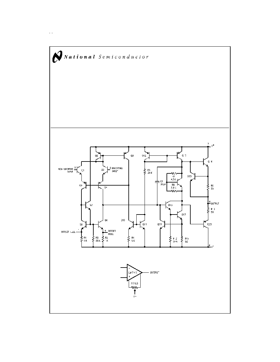
Schematic Diagram
DS009341-1
Offset Nulling Circuit
DS009341-7
May 1998
LM741
Operational
Amplifier
© 1999 National Semiconductor Corporation
DS009341
www.national.com
Absolute Maximum Ratings
(Note 1)
If Military/Aerospace specified devices are required, please contact the National Semiconductor Sales Office/
Distributors for availability and specifications.
(Note 6)
LM741A
LM741E
LM741
LM741C
Supply Voltage
±
22V
±
22V
±
22V
±
18V
Power Dissipation (Note 2)
500 mW
500 mW
500 mW
500 mW
Differential Input Voltage
±
30V
±
30V
±
30V
±
30V
Input Voltage (Note 3)
±
15V
±
15V
±
15V
±
15V
Output Short Circuit Duration
Continuous
Continuous
Continuous
Continuous
Operating Temperature Range
-55∞C to +125∞C
0∞C to +70∞C
-55∞C to +125∞C
0∞C to +70∞C
Storage Temperature Range
-65∞C to +150∞C
-65∞C to +150∞C
-65∞C to +150∞C
-65∞C to +150∞C
Junction Temperature
150∞C
100∞C
150∞C
100∞C
Soldering Information
N-Package (10 seconds)
260∞C
260∞C
260∞C
260∞C
J- or H-Package (10 seconds)
300∞C
300∞C
300∞C
300∞C
M-Package
Vapor Phase (60 seconds)
215∞C
215∞C
215∞C
215∞C
Infrared (15 seconds)
215∞C
215∞C
215∞C
215∞C
See AN-450 "Surface Mounting Methods and Their Effect on Product Reliability" for other methods of soldering
surface mount devices.
ESD Tolerance (Note 7)
400V
400V
400V
400V
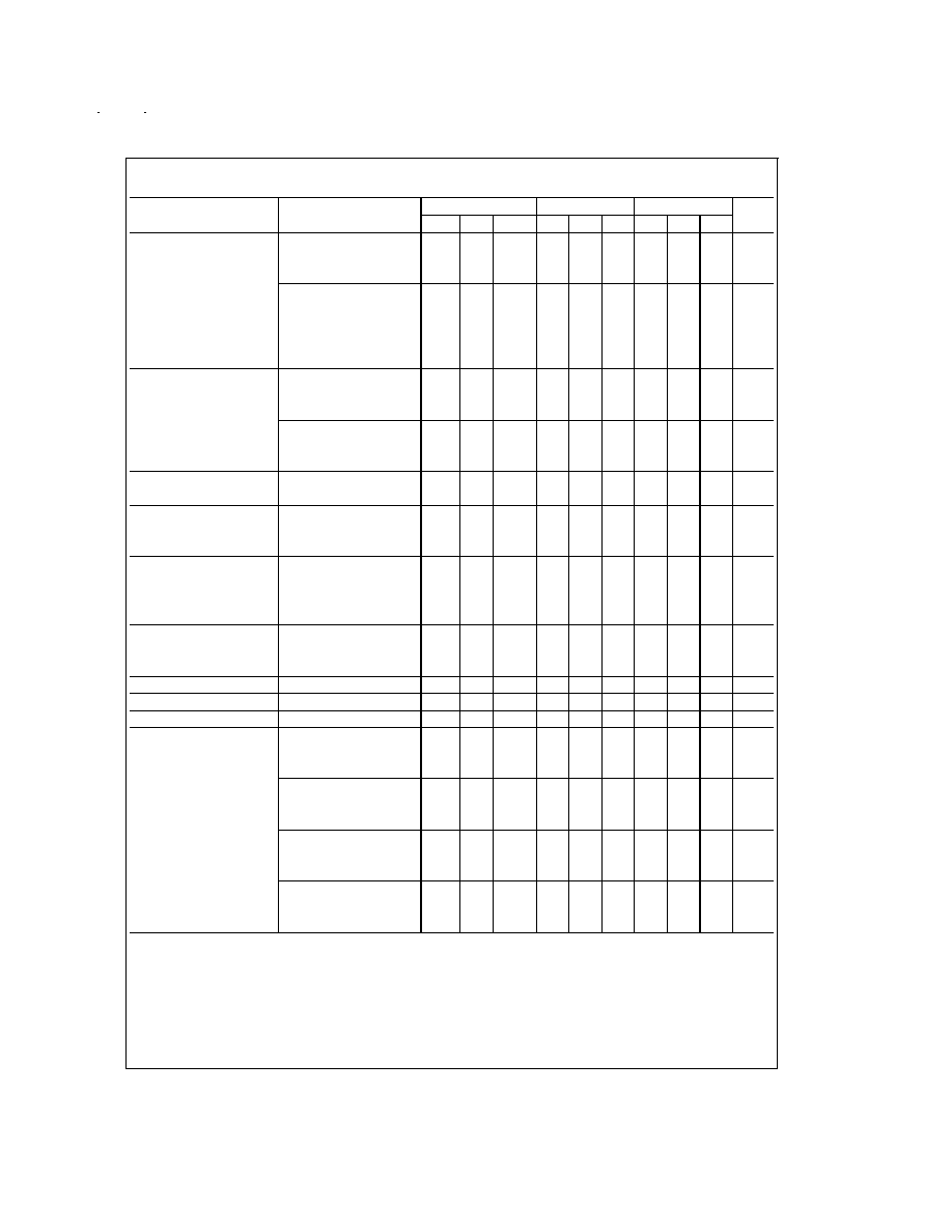
Electrical Characteristics
(Note 4)
Parameter
Conditions
LM741A/LM741E
LM741
LM741C
Units
Min
Typ
Max
Min
Typ
Max
Min
Typ
Max
Input Offset Voltage
T
A
= 25∞C
R
S
10 k
1.0
5.0
2.0
6.0
mV
R
S
50
0.8
3.0
mV
T
AMIN
T
A
T
AMAX
R
S
50
4.0
mV
R
S
10 k
6.0
7.5
mV
Average Input Offset
15
µV/∞C
Voltage Drift
Input Offset Voltage
T
A
= 25∞C, V
S
=
±
20V
±
10
±
15
±
15
mV
Adjustment Range
Input Offset Current
T
A
= 25∞C
3.0
30
20
200
20
200
nA
T
AMIN
T
A
T
AMAX
70
85
500
300
nA
Average Input Offset
0.5
nA/∞C
Current Drift
Input Bias Current
T
A
= 25∞C
30
80
80
500
80
500
nA
T
AMIN
T
A
T
AMAX
0.210
1.5
0.8
µA
Input Resistance
T
A
= 25∞C, V
S
=
±
20V
1.0
6.0
0.3
2.0
0.3
2.0
M
T
AMIN
T
A
T
AMAX
,
0.5
M
V
S
=
±
20V
Input Voltage Range
T
A
= 25∞C
±
12
±
13
V
T
AMIN
T
A
T
AMAX
±
12
±
13
V
www.national.com
2
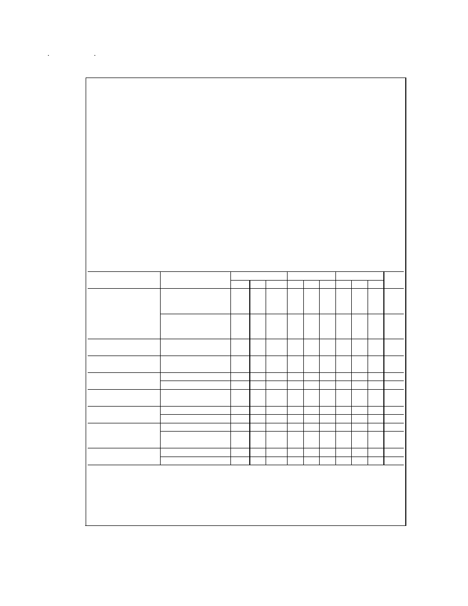
Electrical Characteristics
(Note 4) (Continued)
Note 2: For operation at elevated temperatures, these devices must be derated based on thermal resistance, and T
j
max. (listed under "Absolute Maximum Rat-
ings"). T
j
= T
A
+ (
jA
P
D
).
Thermal Resistance
Cerdip (J)
DIP (N)
HO8 (H)
SO-8 (M)
jA
(Junction to Ambient)
100∞C/W
100∞C/W
170∞C/W
195∞C/W
jC
(Junction to Case)
N/A
N/A
25∞C/W
N/A
Note 3: For supply voltages less than
±
15V, the absolute maximum input voltage is equal to the supply voltage.
Note 4: Unless otherwise specified, these specifications apply for V
S
=
±
15V, -55∞C
T
A
+125∞C (LM741/LM741A). For the LM741C/LM741E, these specifica-
tions are limited to 0∞C
T
A
+70∞C.
Note 5: Calculated value from: BW (MHz) = 0.35/Rise Time(µs).
Note 6: For military specifications see RETS741X for LM741 and RETS741AX for LM741A.
Note 7: Human body model, 1.5 k
in series with 100 pF.
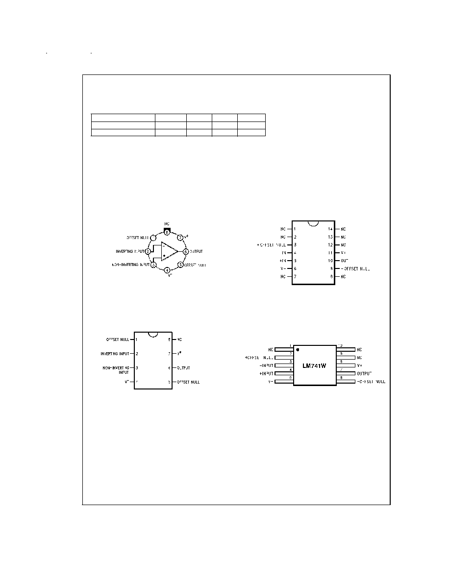
Connection Diagram
Metal Can Package
DS009341-2
Note 8: LM741H is available per JM38510/10101
Order Number LM741H, LM741H/883 (Note 8),
LM741AH/883 or LM741CH
See NS Package Number H08C
Dual-In-Line or S.O. Package
DS009341-3
Order Number LM741J, LM741J/883,
LM741CM, LM741CN or LM741EN
See NS Package Number J08A, M08A or N08E
Ceramic Dual-In-Line Package
DS009341-5
Note 9: also available per JM38510/10101
Note 10: also available per JM38510/10102
Order Number LM741J-14/883 (Note 9),
LM741AJ-14/883 (Note 10)
See NS Package Number J14A
Ceramic Flatpak
DS009341-6
Order Number LM741W/883
See NS Package Number W10A
www.national.com
4
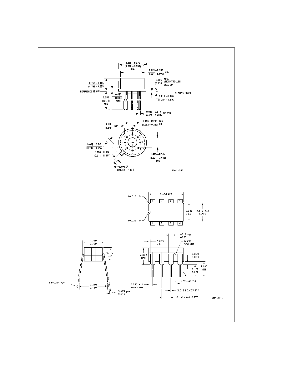
Physical Dimensions
inches (millimeters) unless otherwise noted
Metal Can Package (H)
Order Number LM741H, LM741H/883, LM741AH/883, LM741CH or LM741EH
NS Package Number H08C
Ceramic Dual-In-Line Package (J)
Order Number LM741CJ or LM741J/883
NS Package Number J08A
www.national.com
5