 | –≠–ª–µ–∫—Ç—Ä–æ–Ω–Ω—ã–π –∫–æ–º–ø–æ–Ω–µ–Ω—Ç: LM77 | –°–∫–∞—á–∞—Ç—å:  PDF PDF  ZIP ZIP |
LM77
9-Bit + Sign Digital Temperature Sensor and Thermal
Window Comparator with Two-Wire Interface
General Description
The LM77 is a digital temperature sensor and thermal win-
dow comparator with an I
2
C
TM
Serial Bus interface. The
window-comparator architecture of the LM77 eases the de-
sign of temperature control systems conforming to the ACPI
(Advanced Configuration and Power Interface) specification
for personal computers. The open-drain Interrupt (INT) out-
put becomes active whenever temperature goes outside a
programmable window, while a separate Critical Tempera-
ture Alarm (T_CRIT_A) output becomes active when the
temperature exceeds a programmable critical limit. The INT
output can operate in either a comparator or event mode,
while the T_CRIT_A output operates in comparator mode
only.
The host can program both the upper and lower limits of the
window as well as the critical temperature limit. Program-
mable hysterisis as well as a fault queue are available to
minimize false tripping. Two pins (A0, A1) are available for
address selection. The sensor powers up with default thresh-
olds of 2∞C T
HYST
, 10∞C T
LOW
, 64∞C T
HIGH
, and 80∞C
T_CRIT.
The LM77's 3.0V to 5.5V supply voltage range, Serial Bus
interface, 9-bit + sign output, and full-scale range of over
128∞C make it ideal for a wide range of applications. These
include thermal management and protection applications in
personal computers, electronic test equipment, office elec-
tronics, automotive, and HVAC applications.
Features
n
Window comparison simplifies design of ACPI
compatible temperature monitoring and control.
n
Serial Bus interface
n
Separate open-drain outputs for Interrupt and Critical
Temperature shutdown
n
Shutdown mode to minimize power consumption
n
Up to 4 LM77s can be connected to a single bus
n
9-bit + sign output; full-scale reading of over 128∞C
n
SOP and MSOP 8-lead packages
Key Specifications
j
Supply Voltage
3.0V to 5.5V
j
Supply Current
operating
250 µA (typ)
500 µA (max)
shutdown
5 µA (typ)
j
Temperature
Accuracy
-10∞C to 65∞C
±
1.5∞C(max)
-25∞C to 100∞C
±
2∞C(max)
-55∞C to 125∞C
±
3∞C(max)
Applications
n
System Thermal Management
n
Personal Computers
n
Office Electronics
n
Electronic Test Equipment
n
Automotive
n
HVAC
I2C
Æ
is a registered trademark of Philips Corporation.
July 2001
LM77
9-Bit
+
Sign
Digital
T
emperature
Sensor
and
Thermal
W
indow
Comparator
with
T
wo-W
ire
Interface
© 2001 National Semiconductor Corporation
DS100136
www.national.com
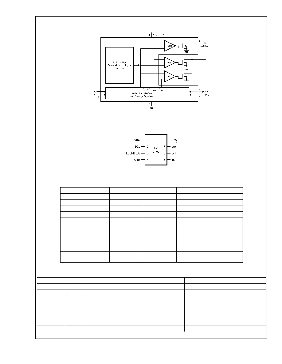
Simplified Block Diagram
Connection Diagram
Ordering Information
Order Number
Supply Voltage
Package
Supplied In
LM77CIM-3
3.3V
SOP8, M08A
Rail
LM77CIMX-3
3.3V
SOP8, M08A
2500 Units on Tape and Reel
LM77CIM-5
5V
SOP8, M08A
Rail
LM77CIMX-5
5V
SOP8, M08A
2500 Units on Tape and Reel
LM77CIMM-3
3.3V
MSOP8,
MUA08A
Rail
LM77CIMMX-3
3.3V
MSOP8,
MUA08A
3500 Units on Tape and Reel
LM77CIMM-5
5V
MSOP8,
MUA08A
Rail
LM77CIMMX-5
5V
MSOP8,
MUA08A
3500 Units on Tape and Reel
Pin Description
Label
Pin #
Function
Typical Connection
SDA
1
Serial Bi-Directional Data Line. Open Drain Output
From Controller
SCL
2
Serial Bus Clock Input
From Controller
T_CRIT_A
3
Critical Temperature Alarm Open Drain Output
Pull Up Resistor, Controller Interrupt Line
or System Hardware Shutdown
GND
4
Power Supply Ground
Ground
INT
5
Interrupt Open Drain Output
Pull Up Resistor, Controller Interrupt Line
+V
S
8
Positive Supply Voltage Input
DC Voltage from 3V to 5.5V
A0≠A1
7,6
User-Set Address Inputs
Ground (Low, "0") or +V
S
(High, "1")
DS100136-1
SOP8 or MSOP
DS100136-2
LM77 See NS Package Number M08A or MM08A
LM77
www.national.com
2
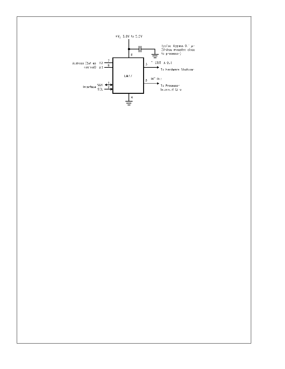
Pin Description
(Continued)
DS100136-3
FIGURE 1. Typical Application
LM77
www.national.com
3
Absolute Maximum Ratings
(Note 1)
Supply Voltage
-0.3V to 6.5V
Voltage at any Pin
-0.3V to (+V
S
+ 0.3V )
Input Current at any Pin
5 mA
Package Input Current (Note 2)
20 mA
T_CRIT_A and INT Output Sink
Current
10 mA
T_CRIT_A and INT Output
Voltage
6.5V
Storage Temperature
-65∞C to +125∞C
Soldering Information, Lead
Temperature
SOP and MSOP Package (Note 3)
Vapor Phase (60 seconds)
215∞C
Infrared (15 seconds)
220∞C
ESD Susceptibility (Note 4)
Human Body Model
2500V
Machine Model
250V
Operating Ratings
(Notes 1, 5)
Specified Temperature Range
T
MIN
to T
MAX
(Note 6)
-55∞C to +125∞C
Supply Voltage Range (+V
S
)(Note 7)
+3.0V to +5.5V
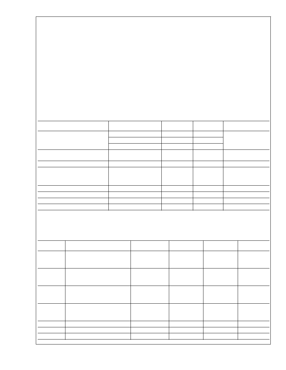
Temperature-to-Digital Converter Characteristics
Unless otherwise noted, these specifications apply for +V
S
=+5 Vdc
±
10% for LM77CIM-5, LM77CIMM-5 and +V
S
=+3.3 Vdc
±
10% for LM77CIM-3, LM77CIMM-3 (Note 7). Boldface limits apply for T
A
= T
J
= T
MIN
to T
MAX
; all other limits T
A
=
T
J
=+25∞C, unless otherwise noted.
Parameter
Conditions
Typical
(Note 8)
Limits
(Note 9)
Units
(Limit)
Accuracy
T
A
= -10∞C to +65∞C
±
1.5
∞C (max)
T
A
= -25∞C to +100∞C
±
2.0
T
A
= -55∞C to +125∞C
±
3.0
Resolution
(Note 10)
10
0.5
Bits
∞C
Temperature Conversion Time
(Note 11)
70
125
ms
Quiescent Current
I
2
C Inactive
0.25
mA
I
2
C Active
0.25
0.5
mA (max)
Shutdown Mode
5
10
µA
T
HYST
Default Temperature
(Notes 13, 14)
2
∞C
T
LOW
Default Temperature
(Note 14)
10
∞C
T
HIGH
Default Temperature
(Note 14)
64
∞C
T
C
Default Temperature
(Note 14)
80
∞C
Logic Electrical Characteristics
DIGITAL DC CHARACTERISTICS Unless otherwise noted, these specifications apply for +V
S
=+5 Vdc
±
10% for LM77CIM-5,
LM77CIMM-5 and +V
S
=+3.3 Vdc
±
10% for LM77CIM-3, LM77CIMM-3. Boldface limits apply for T
A
= T
J
= T
MIN
to T
MAX
; all
other limits T
A
= T
J
=+25∞C, unless otherwise noted.
Symbol
Parameter
Conditions
Typical
(Note 8)
Limits
(Note 9)
Units
(Limit)
V
IN(1)
SDA and SCL Logical "1" Input
Voltage
+V
S
x 0.7
V (min)
+V
S
+0.3
V (max)
V
IN(0)
SDA and SCL Logical "0" Input
Voltage
-0.3
V (min)
+V
S
x 0.3
V (max)
V
IN(1)
A0 and A1 Logical "1" Input
Voltage
2.0
V (min)
+V
S
+0.3
V (max)
V
IN(0)
A0 and A1 Logical "0" Input
Voltage
-0.3
V (min)
0.8
V (max)
I
IN(1)
Logical "1" Input Current
V
IN
= + V
S
0.005
1.0
µA (max)
I
IN(0)
Logical "0" Input Current
V
IN
= 0V
-0.005
-1.0
µA (max)
C
IN
Capacitance of All Digital Inputs
20
pF
LM77
www.national.com
4
Logic Electrical Characteristics
(Continued)
DIGITAL DC CHARACTERISTICS Unless otherwise noted, these specifications apply for +V
S
=+5 Vdc
±
10% for LM77CIM-5,
LM77CIMM-5 and +V
S
=+3.3 Vdc
±
10% for LM77CIM-3, LM77CIMM-3. Boldface limits apply for T
A
= T
J
= T
MIN
to T
MAX
; all
other limits T
A
= T
J
=+25∞C, unless otherwise noted.
Symbol
Parameter
Conditions
Typical
(Note 8)
Limits
(Note 9)
Units
(Limit)
I
OH
High Level Output Current
V
OH
= + V
S
10
µA (max)
V
OL
Low Level Output Voltage
I
OL
= 3 mA
0.4
V (max)
T_CRIT_A Output Saturation
Voltage
I
OUT
= 4.0 mA
(Note 12)
0.8
V (max)
T_CRIT_A Delay
1
Conversions
(max)
t
OF
Output Fall Time
C
L
= 400 pF
250
ns (max)
I
O
= 3 mA
LM77
www.national.com
5