 | –≠–ª–µ–∫—Ç—Ä–æ–Ω–Ω—ã–π –∫–æ–º–ø–æ–Ω–µ–Ω—Ç: LM9074 | –°–∫–∞—á–∞—Ç—å:  PDF PDF  ZIP ZIP |
LM9074
System Voltage Regulator with Keep-Alive ON/OFF
Control
General Description
The LM9074 is a 5V, 3% accurate, 180 mA NPN voltage
regulator. The regulator features an active low delayed reset
output flag which can be used to reset a microprocessor sys-
tem on turn-ON and in the event that the regulator output
falls out of regulation for any reason. An external capacitor
programs a delay time interval before the reset output can
return high.
Designed for automotive application the LM9074 contains a
variety of protection features such as reverse battery,
over-voltage shutdown, thermal shutdown, input transient
protection and a wide operating temperature range.
A unique two-input logic control scheme is used to enable or
disable the regulator output. An ON/OFF input can be pro-
vided by an ignition switch derived signal while a second,
Keep-Alive input, is generated by a system controller. This
allows for a system to remain ON after ignition has been
switched OFF. The system controller can then execute a
power-down routine and after which command the regulator
OFF to a low quiescent current state (60 µA max).
Design techniques have been employed to allow the regula-
tor to remain operational and not generate false reset signals
when subjected to high levels of RF energy (300V/m from
2 MHz to 400 MHz).
Features
n
Automotive application reliability
n
3% output voltage tolerance
n
Insensitive to radiated RFI
n
Dropout voltage less than 2.5V with 180 mA output
current
n
Externally programmed reset delay interval
n
Keep-alive feature with 2 logic control inputs
n
60V Load dump transient protection
n
Thermal shutdown
n
Short circuit protection and disable safety features
n
Reverse battery protection
n
Low OFF quiescent current, 60 µA maximum
n
Wide operating temperature range -40∞C to +125∞C
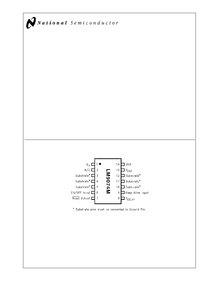
Connection Diagrams and Ordering Information
(Top View)
14-Pin SO Package
DS101305-2
Order Number LM9074M
See NS Package Number M14A
PRELIMINARY
January 2000
LM9074
System
V
oltage
Regulator
with
Keep-Alive
ON/OFF
Control
© 2000 National Semiconductor Corporation
DS101305
www.national.com
Absolute Maximum Ratings
(Note 1)
Input Voltage
ON/OFF, Keep-Alive Inputs
(through 1 k
)
DC Input Voltage
-26V to +26V
Positive Input Transient (t
<
100 ms)
40V
Negative Input Transient (t
<
1 ms)
-50V
Reset Output Sink Current
5 mA
Power Dissipation
Internally Limited
Junction Temperature
150∞C
ESD Susceptibility (Note 2)
12 kV, 2 kV
Lead Temperature
(Soldering, 10 seconds)
260∞C
Storage Temperature
-50∞C to +150∞C
Operating Ratings
(Note 1)
Input Voltage
7.5V to 16.5V
Ambient Temperature
-40∞C to +125∞C
j-pins, M14A Package
30∞C/W
ja, M14A Package
137∞C/W
Electrical Characteristics
The following specifications apply for V
CC
= 7.5V to 16.5V, -40∞C
T
A
125∞C, unless otherwise specified. C
OUT
=0.1µF.
Symbol
Parameter
Conditions
Min
Max
Units
REGULATOR OUTPUT
V
OUT
Output Voltage
20 mA
I
OUT
180 mA
4.85
5.15
V
V
OUT
Line
Line Regulation
I
OUT
= 20 mA, 9V
V
IN
16.5V
I
OUT
= 20 mA, 7.5V
V
IN
16.5V
25
50
mV
mV
V
OUT
Load
Load Regulation
V
IN
= 14.4V, 20 mA
I
OUT
180
mA
50
mV
Iq
Quiescent Current
4V
V
ON/OFF
V
IN
20mA
I
OUT
180mA
25
mA
Ioff
OFF Quiescent Current
V
IN
16.5V, Regulator OFF
-40∞C
T
J
60∞C
60∞C
T
J
135∞C
20
60
µA
µA
Vdo
Dropout Voltage
I
OUT
= 20 mA
I
OUT
= 180 mA
2.0
2.5
V
V
Isc
Short Circuit Current
R
L
= 1
0.4
1.0
A
PSRR
Ripple Rejection
V
IN
= (14V
DC
) + (1V
RMS
@
120Hz)
I
OUT
= 50 mA
60
dB
Voth
OFF
Safety V
OUT
Latch-OFF Threshold
In Keep-Alive mode
V
ON/OFF
= 0V, V
KA
= 0V
4
4.5
V
Vo Transient
V
OUT
during Transients
V
IN
Peak
40V,
R
L
= 100
,
= 100 ms
5.5
V
RESET OUTPUT
Vth
Threshold Voltage
V
OUT
Required to Generate a
Reset Output
4.85V
V
OUT
5.15V
-300
-500
mV
Vlow
Reset Output Low Voltage
Isink = 1.6 mA, V
OUT
>
3.2V
0.4
V
1.4V
V
OUT
3.2V
0.8
V
Vhigh
Reset Output High Voltage
0.9 V
OUT
V
OUT
V
t
delay
Delay Time
Cdelay = 0.1 µFd
7
45
ms
I
delay
Charging Current for Cdelay
-7
25
µA
Rpu
Internal Pull-up Resistance
12
80
k
CONTROL LOGIC
V
KA
low
Low Input Threshold Voltage,
Keep-Alive Input
3.5V
V
OUT
5.25V
0.3 V
OUT
0.5 V
OUT
V
V
KA
high
High Input Threshold Voltage,
Keep-Alive Input
3.5V
V
OUT
5.25V
0.6 V
OUT
0.8 V
OUT
V
V
ON/OFF
low
Low Input Voltage, ON/OFF Input
Rseries = 1 k
-2
2
V
V
ON/OFF
high
High Input Voltage, ON/OFF Input
Rseries = 1 k
4
V
IN
V
LM9074
www.national.com
2
Electrical Characteristics
(Continued)
The following specifications apply for V
CC
= 7.5V to 16.5V, -40∞C
T
A
125∞C, unless otherwise specified. C
OUT
=0.1µF.
Symbol
Parameter
Conditions
Min
Max
Units
CONTROL LOGIC
I
ON/OFF
Input Current, ON/OFF Input
V
ON/OFF
4V
330
µA
4V
<
V
ON/OFF
<
7V
670
µA
V
ON/OFF
7V
10
mA
Rpu
KA
Internal Pull-up Resistance,
Keep-Alive Input
20
100
k
Rpd
ON/OFF
Internal Pull-down Resistance
ON/OFF Input
50
210
k
Note 1: Absolute Maximum Ratings indicate limits beyond which damage to the device may occur. Operating Ratings indicate conditions for which the device is
intended to be functional, but do not guarantee specific performance limits. For guaranteed specifications and conditions, see the Electrical Characteristics.
Note 2: All pins will survive an ESD impulse of
±
2000V using the human body model of 100 pF discharged through a 1.5 k
resistor. In addition, input pins V
IN
and
the ON/OFF input will withstand ten pulses of
±
12 kV from a 150 pF capacitor discharged through a 560
resistor with each pin bypassed with a 22 nF, 100V ca-
pacitor.
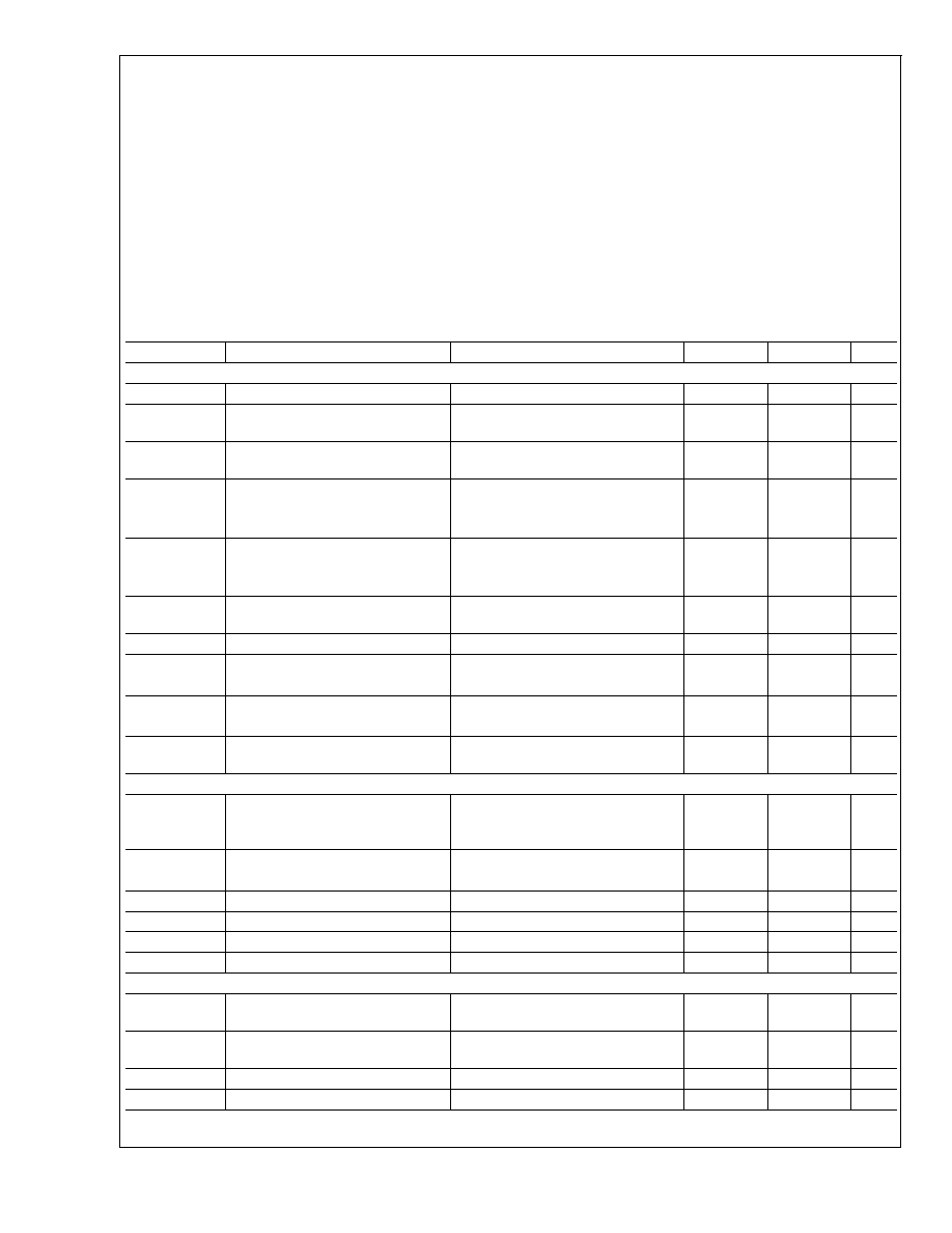
Reset Operation and Protection Features
Typical Performance Characteristics
(T
A
= 25∞C unless indicated otherwise)
DS101305-5
Turn ON Characteristics
DS101305-6
Turn OFF Characteristics
DS101305-7
LM9074
www.national.com
3
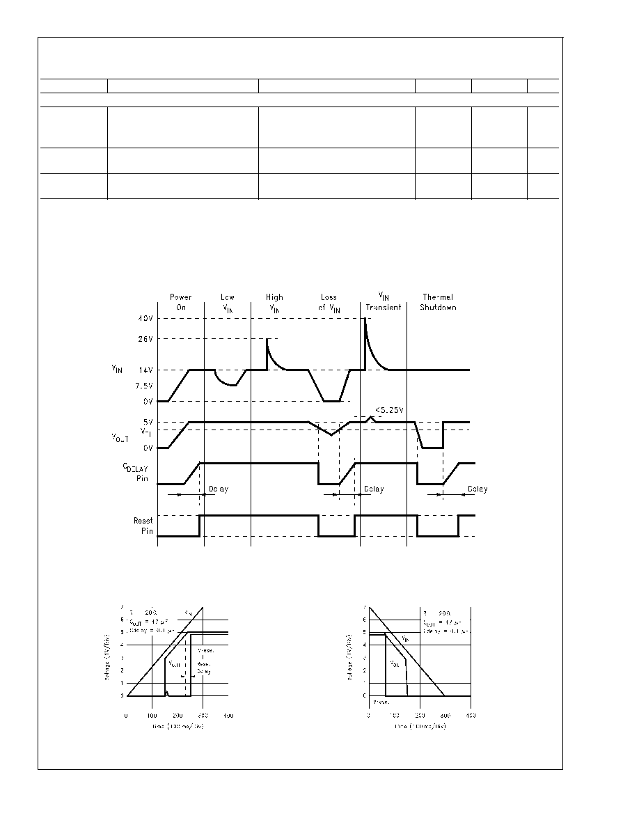
Typical Performance Characteristics
(T
A
= 25∞C unless indicated otherwise) (Continued)
ON/OFF, Keep-Alive and Safety Latch-Off Control Diagrams
Note: If Keep-Alive is provided by a microprocessor powered by the output voltage of the LM9074, the logic "1" voltage level will track V
OUT
as the regulator turns
OFF.
Reset Delay Time
vs Temperature
DS101305-13
Simple ON/OFF control
(Keep-Alive input must be high to turn OFF output)
DS101305-18
Keep-Alive Mode; Turn ON with ON/OFF control,
Keep output biased with Keep-Alive input,
Turn OFF with Keep-Alive (Keep-Alive low keeps
output ON, Keep-Alive going high turns output OFF)
DS101305-19
Switch ON with ON/OFF input; Keep output
biased with Keep-Alive; Hold ouput ON with
ON/OFF; Turn OFF with ON/OFF input.
(Temporary Keep-Alive Mode)
DS101305-20
Safety Latch OFF of V
OUT
when in Keep-Alive Mode
(ON/OFF going high required to turn Output back ON)
DS101305-21
LM9074
www.national.com
4
Control Logic Truth Table
ON/OFF
Input
Keep-Alive
Input
Output
Voltage
Reset
Output
Operating Condition
L
X
0V
L
Low quiescent current standby (OFF) condition
X
5V
after delay
Output turns ON
H
X
5V
H
Normal ON condition
H
0V
L
Output turns OFF
L
5V
H
Output kept ON by Keep-Alive Input
L
5V
H
Output remains ON (or turns ON)
H
X
V
OUT
-300 mV
L
Output pulled out of regulation, reset flag generated
L
L
V
OUT
4V
L
Output latches OFF
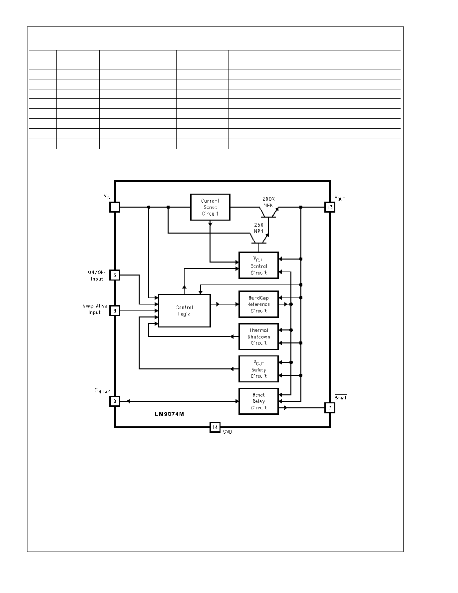
Block Diagram
Application Information
The LM9074 voltage regulator has been optimized for use in
microprocessor based automotive systems. Several unique
design features have been incorporated to address many
FMEA (Failure Mode Effects Analysis) concerns for fail-safe
system performance.
FAULT TOLERANT FEATURES
While not specifically guaranteed due to production testing
limitations, the LM9074 has been tested and shown to con-
tinue to provide a regulated output and, not generate an er-
roneous system reset signal while subjected to high levels of
RF electric field energy (up to 300 V/m signal strength over
a 2 MHz to 400 MHz frequency range). This is very important
in vehicle safety related applications where the system must
continue to operate normally. To maintain this immunity to
RFI the output bypass capacitor is important (47 µF is rec-
ommended).
This regulator is suitable for applications where continuous
connection to the battery is required (
Refer to the Typical Ap-
plication Circuit ). ON/OFF control of the regulator and sys-
tem can be accomplished by switching the ON/OFF input to
the battery or ignition supply V
IN
supply through a SPST
switch. If this input becomes open circuited, an internal
pull-down resistor ensures that the regulator turns OFF.
When the regulator is switched OFF the current load on the
DS101305-22
LM9074
www.national.com
5

Application Information
(Continued)
battery drops to less than 60 µA. With the possibility in many
applications for V
IN
and the ON/OFF input pins to be con-
nected in a system through long lengths of wire, the ESD
protection of these pins has been increased to 12 kV with the
addition of small input bypass capacitors.
An output bypass capacitor of at least 0.1µF is required for
stability (47 µF is recommended). An input capacitor of 1 µF
or larger is recommended to improve line transient and noise
performance.
With the Keep-Alive input, a system microprocessor has the
ability to keep the regulator ON (with a logic "0" on
Keep-Alive) after the ON/OFF input has been commanded
OFF. A power-down sequence, when system variables are
typically stored in programmable memory, can be executed
and take as much time as necessary. At the end of the op-
eration the micro then pulls Keep-Alive high and the regula-
tor and system turn OFF and revert to the low quiescent cur-
rent standby mode.
For additional system reliability, consideration has been
made for the possibility of a short circuited load at the output
of the regulator. When the regulator is switched ON, conven-
tional current limiting and thermal shutdown protect the regu-
lator. When the regulator is switched OFF however, a
grounded V
CC
supply to the micro (due to the shorted regu-
lator output) will force the Keep-Alive input to be low and
thus try to maintain the Keep-Alive mode of operation. With
a shorted load, the drain on the battery could be as high as
1.5A. A separate internal circuit monitors the output voltage
of the regulator. If V
OUT
is less than 4V, as would be the case
with a shorted load, the Keep-Alive function is logically dis-
abled to ensure that the regulator turns OFF and reverts to
less than a 60 µA load on the battery.
Conventional load dump protection is built in to withstand up
to +60V and -50V transients. A 1 k
resistor in series with
the ON/OFF and Keep-Alive inputs are recommended to
provide the same level of transient protection for these pins
if required. Protection against reverse polarity battery con-
nections is also built in. With a reversed battery the output of
the LM9074 will not go more negative than one diode drop
below ground. This will prevent damage to any of the 5V load
circuits.
For applications where the control logic is not required the
logic pins should be configured as shown in
Figure 2. A
separate device, called the LM9071, can be used. The
LM9071 is available in a 5-lead TO-220 package and does
not provide control logic functions, but still retains all of the
protection features of the LM9074.
RESET FLAG
Excessive loading of the output to the point where the output
voltage drops by 300 mV to 500 mV will signal a reset flag to
the micro. This will warn of a V
CC
supply that may produce
unpredictable operation of the system. On power-up and re-
covery from a fault condition the delay capacitor is used to
hold the micro in a reset condition for a programmable time
interval to allow the system operating voltages and
clock to stabilize before executing code. The typical delay
time interval can be estimated using the following equation:
DS101305-23
FIGURE 1. Typical Application Circuit
DS101305-24
FIGURE 2. Control Logic Not Used
LM9074
www.national.com
6

Application Information
(Continued)
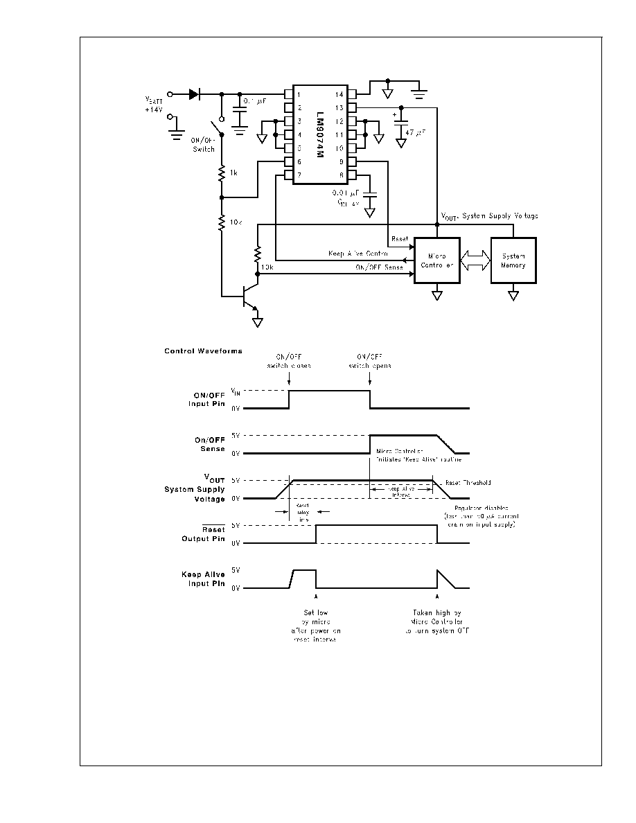
MICROPROCESSOR SYSTEM REGULATOR WITH
KEEP-ALIVE INTERVAL AT TURN-OFF
The following circuit illustrates a system application utilizing
both of the logic control inputs of the LM9074. Closing the
ON/OFF switch powers ON the system. Once powered, the
system controller sets the Keep-Alive line low. The NPN
transistor is used only to signal the controller that the ON/
OFF switch has been opened and the system is to be turned
OFF. Upon detecting this high level at the ON/OFF Sense in-
put line, the controller can then perform a power down rou-
tine. The system will remain fully powered until the controller
commands total shut down by taking the Keep-Alive line
high. The system then shuts OFF and reverts to a very low
current drain standby condition until switched back on.
DS101305-26
LM9074
www.national.com
7
Application Information
(Continued)
DS101305-25
LM9074
www.national.com
8
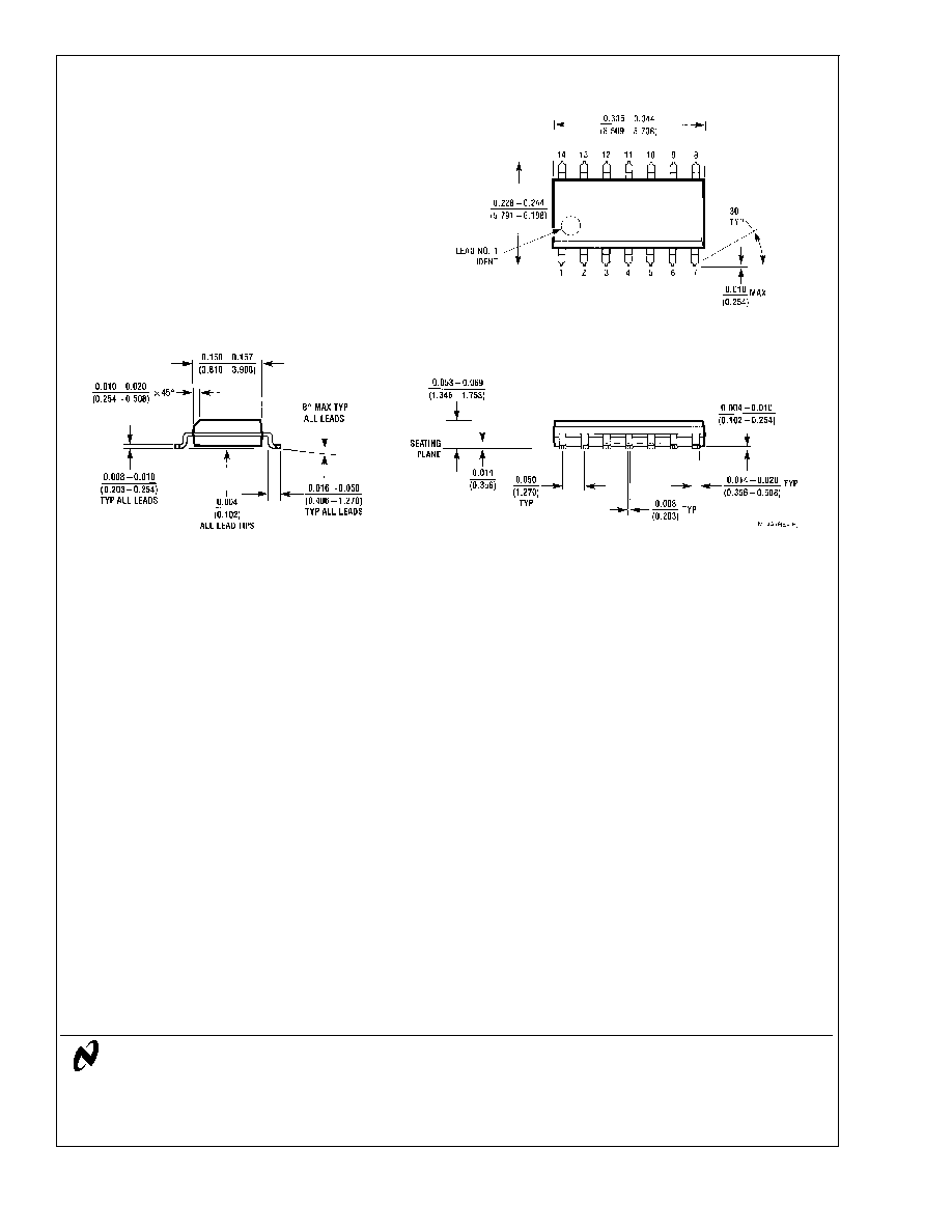
Physical Dimensions
inches (millimeters) unless otherwise noted
LIFE SUPPORT POLICY
NATIONAL'S PRODUCTS ARE NOT AUTHORIZED FOR USE AS CRITICAL COMPONENTS IN LIFE SUPPORT
DEVICES OR SYSTEMS WITHOUT THE EXPRESS WRITTEN APPROVAL OF THE PRESIDENT AND GENERAL
COUNSEL OF NATIONAL SEMICONDUCTOR CORPORATION. As used herein:
1. Life support devices or systems are devices or
systems which, (a) are intended for surgical implant
into the body, or (b) support or sustain life, and
whose failure to perform when properly used in
accordance with instructions for use provided in the
labeling, can be reasonably expected to result in a
significant injury to the user.
2. A critical component is any component of a life
support device or system whose failure to perform
can be reasonably expected to cause the failure of
the life support device or system, or to affect its
safety or effectiveness.
National Semiconductor
Corporation
Americas
Tel: 1-800-272-9959
Fax: 1-800-737-7018
Email: support@nsc.com
National Semiconductor
Europe
Fax: +49 (0) 1 80-530 85 86
Email: europe.support@nsc.com
Deutsch Tel: +49 (0) 1 80-530 85 85
English
Tel: +49 (0) 1 80-532 78 32
FranÁais Tel: +49 (0) 1 80-532 93 58
Italiano
Tel: +49 (0) 1 80-534 16 80
National Semiconductor
Asia Pacific Customer
Response Group
Tel: 65-2544466
Fax: 65-2504466
Email: sea.support@nsc.com
National Semiconductor
Japan Ltd.
Tel: 81-3-5639-7560
Fax: 81-3-5639-7507
www.national.com
14-Lead (0.150' Wide) Molded SO Package
Order Number LM9074M
NS Package Number M14A
LM9074
System
V
oltage
Regulator
with
Keep-Alive
ON/OFF
Control
National does not assume any responsibility for use of any circuitry described, no circuit patent licenses are implied and National reserves the right at any time without notice to change said circuitry and specifications.