©1997 NSC
1
http://www.national.com
LMC7532
Low EMI, Low Power XGA/SVGA TFT-LCD Column Driver
General description
The LMC7532 is a Column Driver suitable for Nation-
al's Reduced Swing Differential Signalling (RSDS)
digital interface. It converts this 18-bit digital data into
analog voltage for 300 or 309 columns, charging each
sub-pixel to the correct gray level corresponding to the
digital value.
The RSDS path to the panel timing controller contrib-
utes toward lowering radiated EMI, reducing system
power consumption and eliminates one of the two pix-
el busses used in typical XGA TFT-LCD panels today.
This single 9-bit differential bus conveys the 18-bit
color data for XGA panels at 130Mb/s when using
VESA 60 Hz standard timing.
With the addition of a single National DS90CF364 or
`564 FPD-LinkTM chip, and the FPD63310 Universal
Interface XGA/SVGA Timing controller, the entire data
path is optimized for reduced EMI, power consump-
tion and width.
Feature
s
Reduced Swing Differential Signalling (RSDS)
TM
digital bus reduces power, EMI and width from tim-
ing controller.
s
Selectable 300/309 outputs provides ability to
drive SVGA and XGA TFT-LCD systems.
s
Switched reference type DAC gives high accuracy
with low reference current requirements.
s
Clock Frequency up to:
65MHZ
s
Typical Accuracy:
+/-5 mV
s
Narrow bus.
s
64 gray scales.
s
Receive RSDS @ 130Mb/s width @ 65MHz clock
from FPD 63310.
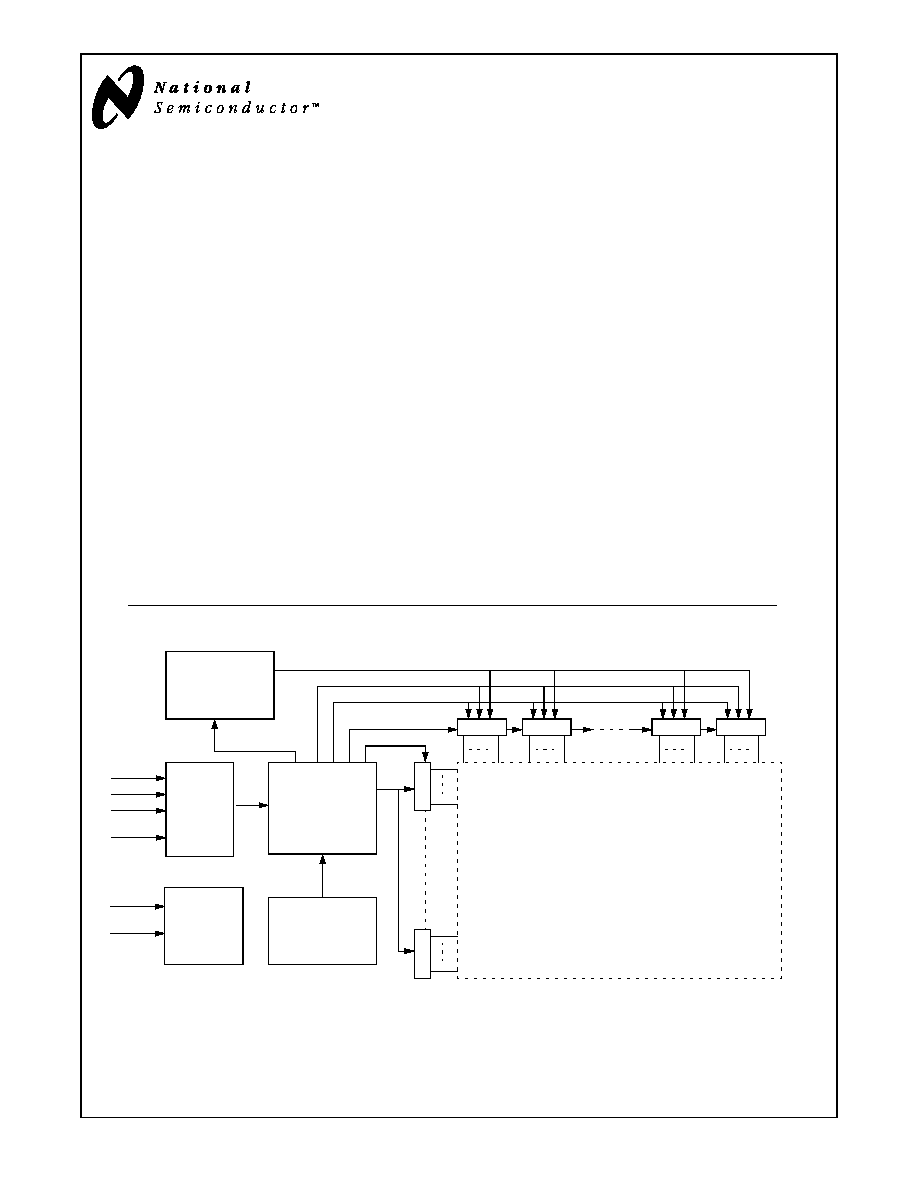
System Diagram
Gray scale
Reference
FPD63310
XGA Panel
Timing
Controller
NM93CSxxL
Serial EEPROM
DS
90CF
564
/
364
F
P
D
-
Li
nk
Panel
Power
Supply
/2 Link1
/2 Link2
/2 Link3
/2 LinkC
LMC7532
LMC7532
LMC7532
LMC7532
1024 X 768 or 800 X 600
TFT-LCD Array
VDD
VSS
R
A
R
E
Start Pulse
Start Pulse
Ga
t
e
C
l
o
c
k
Inversion
Control
/9 + CLK, RSDS BUS
Line Transfer Signal
Gray Scale Voltage Reference BUS
1
n
1
n
1
n
1
n
A1
An
E1
En
FIGURE 1. Block diagram of the LCD module
FPD-LinkTM is a trademark of National Semiconductor
ADVANCED INFORMATION
NOV, 1997
National does not assume any responsibility for use of any circuitry described, no circuit patent licenses are implied and National reserves the right at any time without notice to change said circuitry and specifications.
LIFE SUPPORT POLICY
NATIONAL'S PRODUCTS ARE NOT AUTHORIZED FOR USE AS CRITICAL COMPONENTS IN LIFE SUPPORT
DEVICES OR SYSTEMS WITHOUT THE EXPRESS WRITTEN APPROVAL OF THE PRESIDENT OF NATIONAL
SEMICONDUCTOR CORPORATION. As used herein:
1. Life support devices or systems are devices or systems
which, (a) are intended for surgical implant into the body,
or (b) support or sustain life, and whose failure to per-
form, when properly used in accordance with instructions
for use provided in the labeling, can be reasonably ex-
pected to result in a significant injury to the user.
2. A critical component is any component of a life support
device or system whose failure to perform can be rea-
sonably expected to cause the failure of the life support
device or system, or to affect its safety or effectiveness.
National Semiconductor
Corporation
Tel: 1-800-272-9959
Fax: 1-800-737-7018
Email: support@nsc.com
National Semiconductor
Europe
Fax:
(+49) 0-180-530 85 86
Email:
europe.support@nsc.com
Deutsch Tel:
(+49) 0-180-530 85 85
English Tel:
(+49) 0-180-532 78 32
National Semiconductor
Japan Ltd.
Tel: 81-3-5620-6175
Fax: 81-3-5620-6179
National Semiconductor
Asia Pacific
Customer Response Group
Tel: 65-254-4466
Fax: 65-250-4466
Email: sea.support@nsc.com
www.national.com
13
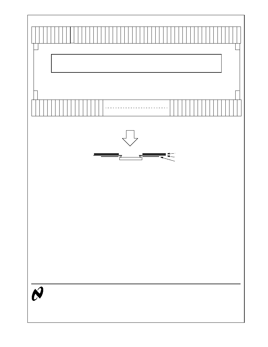
Package Infomation
C
O
M
1
C
O
M
1
A
V
S
S
A
V
D
D
V
O
P
V
R
E
F
1
1
V
R
E
F
9
V
R
E
F
7
V
R
E
F
5
V
R
E
F
3
V
R
E
F
1
D
V
D
D
D
G
N
D
D
V
D
D
R
/
L
D
2
0
P
D
2
0
N
D
2
1
P
D
2
1
N
D
2
2
P
D
2
2
N
T
P
1
E
I
O
2
D
V
D
D
C
L
K
N
C
L
K
P
D
G
N
D
N
O
U
T
3
0
9
E
I
O
1
D
1
0
P
D
1
0
N
D
1
1
P
D
1
1
N
D
1
2
P
D
1
2
N
D
0
0
P
D
0
0
N
D
0
1
P
D
0
1
N
D
0
2
P
D
0
2
N
D
V
D
D
D
G
N
D
V
R
E
F
2
V
R
E
F
4
V
R
E
F
6
V
R
E
F
8
V
R
E
F
1
0
V
O
P
A
V
D
D
A
V
S
S
C
O
M
2
C
O
M
2
C
O
M
1
C
O
M
1
D
U
M
M
Y
D
U
M
M
Y
D
U
M
M
Y
D
U
M
M
Y
C
O
M
2
C
O
M
2
D
U
M
M
Y
D
U
M
M
Y
D
U
M
M
Y
D
U
M
M
Y
O
U
T
3
0
9
O
U
T
3
0
8
O
U
T
3
0
7
O
U
T
3
0
6
O
U
T
3
0
5
O
U
T
3
0
4
O
U
T
3
0
3
O
U
T
3
0
2
O
U
T
3
0
1
O
U
T
3
0
0
O
U
T
2
9
9
O
U
T
2
9
8
O
U
T
0
1
2
O
U
T
0
1
1
O
U
T
0
1
0
O
U
T
0
0
9
O
U
T
0
0
8
O
U
T
0
0
7
O
U
T
0
0
6
O
U
T
0
0
5
O
U
T
0
0
4
O
U
T
0
0
3
O
U
T
0
0
2
O
U
T
0
0
1
LMC7532
Polyimide
Copper
Solder resister
top
View
FIGURE 10. TCP pin assignment
Order number LMC7532CTxx
xx = customer package designator.
LMC7532
D
V
D
D