TL EE12584
NSAM266SA
CompactSPEECH
Digital
Speech
Processor
with
Serial
Flash
Interface
March 1996
NSAM266SA CompactSPEECH
TM
Digital Speech
Processor with Serial Flash Interface
General Description
The NSAM266SA is a member of National Semiconductor's
CompactSPEECH Digital Speech Processor family This
processor provides Digital Answering Machine (DAM) func-
tionality to embedded systems
The CompactSPEECH interfaces with National Semicon-
ductor's NM29A040 and NM29A080 Serial Flash memory
devices to provide a cost-effective solution for DAM and
Cordless DAM (CDAM) applications
The CompactSPEECH processor integrates the functions of
a traditional Digital Signal Processing (DSP) chip and the
CR16A a 16-bit general-purpose RISC core implementation
of the CompactRISC
TM
architecture It contains system sup-
port functions such as Interrupt Control Units Codec inter-
face MICROWIRE
TM
interfaces to a microcontroller and
Serial Flash WATCHDOG
TM
timer and a Clock Generator
The CompactSPEECH processor operates as a slave pe-
ripheral that is controlled by an external microcontroller via
a serial MICROWIRE interface In a typical DAM environ-
ment the microcontroller controls the analog circuits but-
tons and display and activates the CompactSPEECH by
sending it commands The CompactSPEECH processor ex-
ecutes the commands and returns status information to the
microcontroller
The CompactSPEECH firmware implements voice compres-
sion and decompression tone detection and generation
message storage management speech synthesis for time-
and-day stamp and supports user-defined voice prompts in
various languages
The CompactSPEECH implements echo-cancellation tech-
niques to support high-quality DTMF tone detection during
message playback
The CompactSPEECH can synthesize messages in various
languages via the International Vocabulary Support (IVS)
mechanism The NSAM266SA can store vocabularies on
either Serial Flash or Expansion ROM memories DAM
manufacturers can thus create machines that ``speak'' in
different languages simply by using other vocabularies For
more details about IVS refer to the
IVS User's Manual
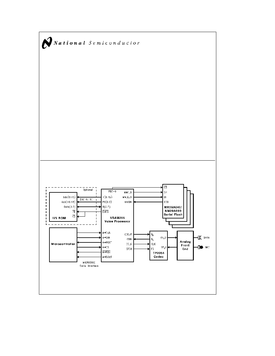
1 0 Hardware
1 1 BLOCK DIAGRAMS
NSAM266SA Basic Configuration
TL EE 12584 ≠ 1
TRI-STATE
is a registered trademark of National Semiconductor Corporation
CompactSPEECH
TM
CompactRISC
TM
COPS
TM
Microcontrollers HPC
TM
MICROWIRE
TM
MICROWIRE PLUS
TM
and WATCHDOG
TM
are trademarks of National Semiconductor Corporation
C1996 National Semiconductor Corporation
RRD-B30M46 Printed in U S A
http
www national com

Features
Y
Designed around the CR16A a 16-bit general-purpose
RISC core implementation of the CompactRISC archi-
tecture
Y
20 48 MHz operation
Y
On-chip DSP Module (DSPM) for high-speed DSP
operations
Y
On-chip codec clock generation and interface
Y
Power-down mode
Y
Selectable speech compression rate of 5 2 kbit s or
7 3 kbit s with silence compression
Y
Up to 16 minutes recording on a 4-Mbit Serial Flash
(more than 1 hour total recording time on four devices)
Y
The number of messages that can be stored is limited
only by memory size
Y
MICROWIRE slave interface to an external
microcontroller
Y
MICROWIRE master interface to Serial Flash memory
devices
Y
Storage and management of messages
Y
Programmable message tag for message categoriza-
tion e g
Mailboxes InComing Messages (ICM) Out-
Going Messages (OGM)
Y
Skip forward or backward during message playback
Y
Digital volume control
Y
Variable speed playback
Y
Supports external vocabularies using Serial Flash or
expansion ROM
Y
Multi-lingual speech synthesis using International Vo-
cabulary Support (IVS)
Y
Vocabularies available in English Japanese Mandarin
German French and Spanish
Y
DTMF generation and detection
Y
DTMF detection during OutGoing Message playback
Y
Single tone generation
Y
Telephone line functions including busy and dial tone
detection
Y
Call screening (input signal echoed to codec output)
Y
Real-time clock
Y
Direct access to message memory
Y
Supports long-frame and short-frame codecs
Y
Supports up to four 4-Mbit or two 8-Mbit Serial Flash
devices
Y
Supports prerecorded IVS and OGM on Serial Flash
Y
Available in 68-pin PLCC and 100-pin PQFP packages
http
www national com
2

Table of Contents
1 0 HARDWARE
1 1 Block Diagrams
1 2 Pin Assignment
1 2 1 Pin
Signal Assignment
1 2 2 Pin Assignment in the 68-PLCC Package
1 2 3 Pin Assignment in the 100-PQFP Package
1 3 Functional Description
1 3 1 Resetting
1 3 2 Clocking
1 3 3 Power-down Mode
1 3 4 Power and Grounding
1 3 5 Memory Interface
1 3 6 Codec Interface
1 4 Specifications
1 4 1 Absolute Maximum Ratings
1 4 2 Electrical Characteristics
1 4 3 Switching Characteristics
1 4 4 Synchronous Timing Tables
1 4 5 Timing Diagrams
2 0 SOFTWARE
2 1 Overview
2 1 1 DSP-based Algorithms
2 1 2 System Support
2 1 3 Peripherals Support
2 2 CompactSPEECH Commands
Quick Reference
Table
2 3 The State Machine
2 4 Command Execution
2 5 Tunable Parameters
2 6 Messages
2 6 1 Message Tag
2 7 Speech Compression
2 8 Tone and No-Energy Detection
2 9 Speech Synthesis
2 9 1 Explanation of Terms
2 9 2 Vocabulary Design
2 9 3 IVS Vocabulary Components
2 9 4 The IVS Tool
2 9 5 How to Use the IVS Tool With the
CompactSPEECH
2 10 Initialization
2 11 Microwire Serial Interface
2 12 Signal Description
2 12 1 Signal Use in the Interface Protocol
2 12 2 Interface Protocol Error Handling
2 13 The Master Microwire Interface
2 13 1 Master MICROWIRE Data Transfer
2 14 Command Description
APPENDIX A
SCHEMATIC DIAGRAMS
http
www national com
3

1 0 Hardware
(Continued)
1 2 PIN ASSIGNMENT
The following sections detail the pins of the NSAM266SA
processor Slashes separate the names of signals that
share the same pin
1 2 1 Pin
Signal Assignment
Table 1-1 shows all the pins and the signals that use them
in different configurations It also shows the type and direc-
tion of each signal
TABLE 1-1 CompactSPEECH Pin
Signal Assignment
Pin Name
Type
Signal Name
I O
A(0 15)
TTL
A(0 15)
Output
CCLK
TTL
CCLK
Output
CDIN
TTL
CDIN
Input
CDOUT
TTL
CDOUT
Output
CFS0
TTL
CFS0
Output
D(0 7)
TTL
D(0 7)
I O
MWCS
TTL (Note A)
MWCS
Input
TST
TTL
TST
Input
MWRDY
TTL
MWRDY
I O
MWRQST
TTL
MWRQST
I O
MWDOUT
TTL
MWDOUT
Output
PB(0 2)
TTL
EA(16 18)
Output
(Note B)
PB(3 6)
TTL
CS(0 3)
Output
(Note C)
EMCS
TTL1 (Note D)
EMCS
Output
ENV0
CMOS (Note E)
ENV0
Input
MWCLK
TTL
MWCLK
Input
MWDIN
TTL
MWDIN
Input
MMCLK
TTL1 (Note D)
MMCLK
Output
MMDIN
TTL
MMDIN
Input
MMDOUT
TTL1 (Note D)
MMDOUT
Output
CFS0
CMOS
CFS0
Output
RESET
Schmitt (Note A)
RESET
Input
V
CC
Power
V
CC
V
SS
Power
V
SS
X1
XTAL
X1
OSC
X2 CLKIN
XTAL
X2
OSC
TTL
CLKIN
Input
Note A
Schmitt trigger input
Note B
Virtual address lines for IVS ROM
Note C
Chip select lines for Serial Flash devices
Note D
TTL1 output signals provide CMOS levels in the steady
state for small loads
Note E
Input during reset CMOS level input
http
www national com
4
1 0 Hardware
(Continued)
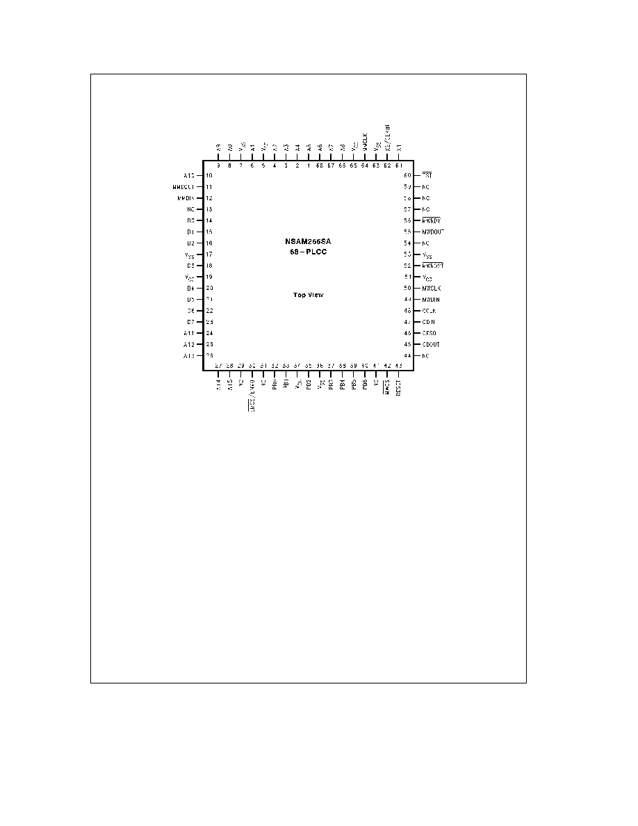
1 2 2 Pin Assignment in the 68-PLCC Package
TL EE 12584 ≠ 3
Note
Pins marked NC should not be connected
FIGURE 1-1 68-PLCC Package Connection Diagram
http
www national com
5