NTE1130
Integrated Circuit
Color TV Demodulator
Features:
D
Color TV Demodulator (Function)
D
Color Difference Signal Amplifier
D
Chroma Demodulator
D
Color Matrix Circuit
D
DC Hue Control
D
High Sensitivity:
Output V
B
≠Y = 2.5V
p≠p
Input 0.2V
p≠p
D
Including MOS Capacitance for Filter
D
Hue is controlled by DC Voltage
Absolute Maximum Ratings: (T
A
= +25
∞
C unless otherwise specified)
Supply Voltage (V
13
), V
CC
18V
. . . . . . . . . . . . . . . . . . . . . . . . . . . . . . . . . . . . . . . . . . . . . . . . . . . . . . . . . . .
Hue Output terminal Voltage, V
12
18V
. . . . . . . . . . . . . . . . . . . . . . . . . . . . . . . . . . . . . . . . . . . . . . . . . . . . .
Hue Control Terminal Voltage, V
9
0 to V
CC
. . . . . . . . . . . . . . . . . . . . . . . . . . . . . . . . . . . . . . . . . . . . . . . . .
Chroma Signal Input, e
C
4V
P≠P
. . . . . . . . . . . . . . . . . . . . . . . . . . . . . . . . . . . . . . . . . . . . . . . . . . . . . . . . . .
Reference Signal Input Voltage, e
R
4V
P≠P
. . . . . . . . . . . . . . . . . . . . . . . . . . . . . . . . . . . . . . . . . . . . . . . . .
Sub≠Carrier Input Voltage, V
10
, V
11
4V
P≠P
. . . . . . . . . . . . . . . . . . . . . . . . . . . . . . . . . . . . . . . . . . . . . . . . .
Minimum Load Resistance, R
L
3k
. . . . . . . . . . . . . . . . . . . . . . . . . . . . . . . . . . . . . . . . . . . . . . . . . . . . . . .
Power Dissipation, P
D
750mW
. . . . . . . . . . . . . . . . . . . . . . . . . . . . . . . . . . . . . . . . . . . . . . . . . . . . . . . . . .
Derate Above 25
∞
C
6.0mW/
∞
C
. . . . . . . . . . . . . . . . . . . . . . . . . . . . . . . . . . . . . . . . . . . . . . . . . . . . .
Operating Temprature Range, T
opr
≠20
∞
to +65
∞
C
. . . . . . . . . . . . . . . . . . . . . . . . . . . . . . . . . . . . . . . . . . .
Storage Temperature Range, T
stg
≠55
∞
to +150
∞
C
. . . . . . . . . . . . . . . . . . . . . . . . . . . . . . . . . . . . . . . . . .
Electrical Characteristics: (T
A
= +25
∞
C, V
CC
= 15V, R
L
= 5.6k
unless otherwise specified)
Parameter
Symbol
Test Conditions
Min
Typ
Max
Unit
Static Characteristics
Operating Supply Voltage
V
CC
13.5
15.0
16.5
V
Output Terminal Voltage
V
14, 15, 16
R
L
= 5.6k
8.8
9.8
10.8
V
Supply Current
I
CC
R
L
=
6.0
10.4
15.0
mA
R
L
= 5.6k
11.0
16.8
23.0
mA
Reference Signal Input Terminal Voltage
V
3
R
L
= 5.6k
≠
5.9
≠
V

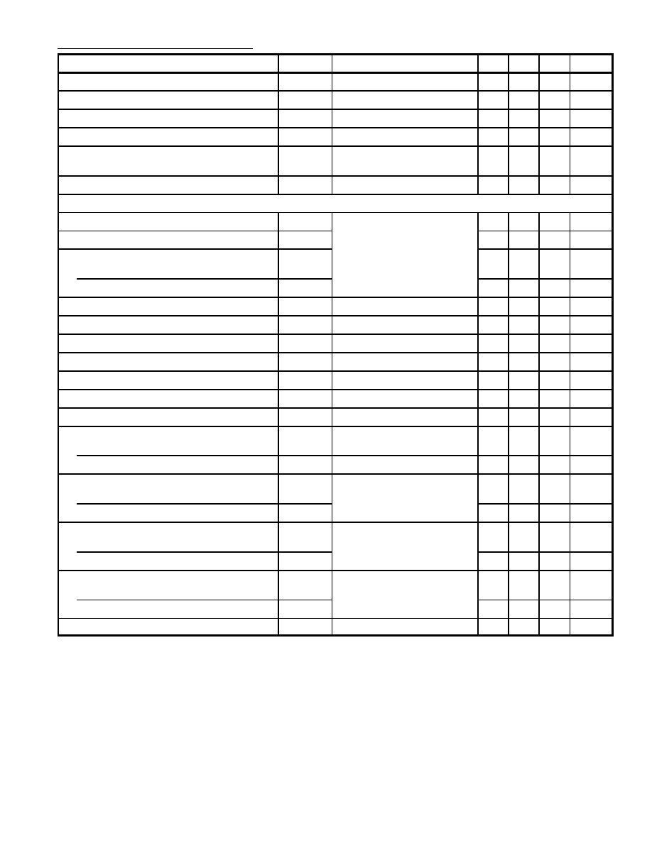
Electrical Characteristics (Cont'd): (T
A
= +25
∞
C, V
CC
= 15V, R
L
= 5.6k
unless otherwise specified)
Parameter
Symbol
Test Conditions
Min
Typ
Max
Unit
Chroma Signal Input Terminal Voltage
V
4
R
L
= 5.6k
≠
3.8
≠
V
Sub≠Carrier Signal Input Terminal Voltage
V
10
R
L
= 5.6k
≠
1.35
≠
V
Difference Voltage Between Terminals
R
L
= 5.6k
≠
≠
0.4
V
Output Voltage Temperature Coefficient
R
L
= 5.6k
≠3.0
≠
+3.0
mV/
∞
C
Output Difference Voltage Temperature
Coefficient
R
L
= 5.6k
≠2.0
≠
+2.0
mV/
∞
C
Hue Circuit Output Current
I
12
Pin9: Open
≠
2.1
≠
mA
Dynamic Characteristics (f = 3.58MHz)
R≠Y Output Voltage
V
R≠Y
V
B≠Y
= 2.5V
P≠P
, e
r
= 0.5V
P≠P
1.9
2.1
2.3
V
P≠P
G≠Y Output Voltage
V
G≠Y
0.5
0.6
0.7
V
P≠P
Relative Output Phase
R≠Y to B≠Y Output
q
R
110
115
120
deg.
G≠Y to B≠Y Output
q
G
247
255
263
deg.
B≠Y Output Voltage
V
B≠Y
e
R
= 0.5V
P≠P
, e
C
= 1.0V
P≠P
4.5
6.0
≠
V
P≠P
Chroma Signal Input Voltage
e
C
V
B≠Y
= 2.5V
P≠P
, e
R
= 0.5V
P≠P
≠
200
300
V
P≠P
Harmonic Output Voltage
V
B≠Y
= 2.5V
P≠P
≠
≠
0.6
V
P≠P
Residual Carrier Level
e
C
= 0, e
R
= 0.5V
P≠P
≠
50
300
V
P≠P
Hue Output Regulation
Max/Min
≠
≠
1.7
Hue Max. Output Swing
e
i
= 1.0V
P≠P
2.0
≠
≠
V
P≠P
Hue Phase Shift
Pin9: 0 to 15V
70
100
≠
deg.
Sub≠Carrier Terminal Input Impedance
Parallel Input Resistance
r
ip
≠
2.1
≠
k
Parallel Input Capacitance
c
ip
≠
4.0
≠
pF
Reference Signal Terminal Input Impedance
Parallel Input Resistance
r
ip
Pin1, Pin2
≠
2.0
≠
k
Parallel Input Capacitance
c
ip
≠
4.0
≠
pF
Chroma Signal Terminal Input Impedance
Parallel Input Resistance
r
ip
Pin5, Pin6
≠
2.0
≠
k
Parallel Input Capacitance
c
ip
≠
4.0
≠
pF
Hue Circuit Terminal Input Impedance
Parallel Input Resistance
r
ip
Pin12
≠
100
≠
k
Parallel Input Capacitance
c
ip
≠
6
≠
pF
Hue Circuit Voltage Gain
G
VH
R
L
= 1k
5
9
13
dB


