
NTE1510
Integrated Circuit
5≠Step LED Driver for Linear Scale
Description:
The NTE1510 is an integrated circuit in an 8≠Lead SIP type package designed for use in level meter
applications. This device is capable of driving 5 LEDs to create a bar≠type display. In accordance
with the input level, the uppermost LED brightness varies to form a linear indicator, making the
NTE1510 ideal for use in signal meters and VU meters. A low≠voltage reference power supply is
built≠in, so that the only external components required are LEDs, resistors, and capacitors.
Features:
D
Bar≠Type Display of Input Level using 5 LEDs
D
The Uppermost LED Brightness Varies Linearly With Respect to the Input Level Resulting in a
High≠Resolution Display with No Radiation.
D
Built≠In Reference Supply
D
By Changing the External Reference Values, the LED Brightness can be Adjusted
D
Wide Range of Supply Voltages: V
CC
= 4V to 18V
D
High Input Impedance: I
IN
= 100nA Typ
Applications:
D
Signal Meters
D
VU Meters
D
Tuning Meters
D
General Purpose Display Applications
Absolute Maximum Ratings: (T
A
= +25
∞
C unless otherwise specified)
Supply Voltage, V
CC
18V
. . . . . . . . . . . . . . . . . . . . . . . . . . . . . . . . . . . . . . . . . . . . . . . . . . . . . . . . . . . . . . . .
Input Voltage, V
IN
6V
. . . . . . . . . . . . . . . . . . . . . . . . . . . . . . . . . . . . . . . . . . . . . . . . . . . . . . . . . . . . . . . . . . .
Output Breakdown Voltage, BV
O
18V
. . . . . . . . . . . . . . . . . . . . . . . . . . . . . . . . . . . . . . . . . . . . . . . . . . . . .
Output Current (Per Pin), I
O
15mA
. . . . . . . . . . . . . . . . . . . . . . . . . . . . . . . . . . . . . . . . . . . . . . . . . . . . . . .
Power Dissipation (Note 1), P
dF
550mW
. . . . . . . . . . . . . . . . . . . . . . . . . . . . . . . . . . . . . . . . . . . . . . . . . . .
Derate Above 25
∞
C
5.5mW/
∞
C
. . . . . . . . . . . . . . . . . . . . . . . . . . . . . . . . . . . . . . . . . . . . . . . . . . . . .
Operating Temperature Range, T
opr
≠20
∞
to +75
∞
C
. . . . . . . . . . . . . . . . . . . . . . . . . . . . . . . . . . . . . . . . .
Storage Temperature Range, T
stg
≠40
∞
to +125
∞
C
. . . . . . . . . . . . . . . . . . . . . . . . . . . . . . . . . . . . . . . . . .
Note 1. With the NTE1510 soldered to a printed circuit board (copper≠clad area 4.5cm x 5.5cm,
thickness 35
µ
, board thickness 2.0mm).
Recommended Operating Conditions:
Supply Voltage Range
4V to 18V
. . . . . . . . . . . . . . . . . . . . . . . . . . . . . . . . . . . . . . . . . . . . . . . . . . . . . . . . .
Rated Supply Voltage
10V
. . . . . . . . . . . . . . . . . . . . . . . . . . . . . . . . . . . . . . . . . . . . . . . . . . . . . . . . . . . . . . .
Electrical Characteristics: (T
A
= +25
∞
C, V
CC
= 10V unless otherwise specified)
Parameter
Symbol
Test Conditions
Min
Typ
Max
Unit
Supply Voltage Range
V
CC
4
10
18
V
Fullscale Input Voltage
V
INF
≠
1320
≠
mV
Step Voltage
V
step
≠
210
≠
mV
Input Current
I
IN
V
IN
= 0V, Note 2
≠
0.1
1.0
µ
A
Circuit Current
I
CC
V
IN
= 0V
≠
5
8
mA
Output 1 LED Drive Voltage (Pin6)
V
IT(6)
R
L
= 1.5k
, I
L
= 100
µ
A,
170
230
300
mV
Output 2 LED Drive Voltage (Pin7)
V
IT(7)
Using red G
a
AIA
s
LEDs
380
450
530
mV
Output 3 LED Drive Voltage (Pin8)
V
IT(8)
580
660
730
mV
Output 4 LED Drive Voltage (Pin1)
V
IT(1)
780
860
940
mV
Output 5 LED Drive Voltage (Pin2)
V
IT(2)
980
1070 1180
mV
Note 2. Current flowing from Pin4 is taken as positive current.
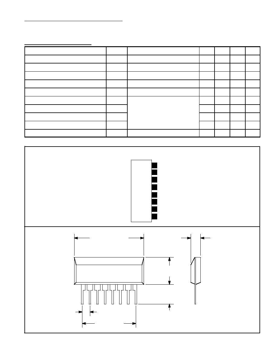
V
CC
Pin Connection Diagram
(Front View)
LED5
Input
LED3
LED4
GND
LED1
LED2
8
7
6
5
4
3
2
1
.118 (3.0) Max
1
8
.100 (2.54) Typ
.165 (4.2)
Min
.264 (6.72)
Max
.768 (19.52) Max
.700 (17.78)