
NTE1648 and NTE1649
Integrated Circuit
Telephone Tone Ringer
Description:
The NTE1648 and NTE1649 are bipolar integrated circuits in an 8≠Lead DIP type package designed
for telephone bell replacement.
Functions:
D
Two Oscillators
D
Output Amplifier
D
Power Supply Control Circuit
Features:
D
Designed for Telephone Bell Replacement
D
Low Current Drain
D
Small Size 8≠Lead MINIDIP Package
D
Adjustable 2≠Frequency Tone
D
Adjustable Warbling Rate
D
Built≠in Hysteresis Prevents False Triggering and Rotary Dial "CHIRPS"
D
Extension Tone Ringer Modules
D
Alarms or Other Altering Devices
D
External Triggering or Ringer Disable (NTE1648)
D
Adjustable for Reduced Supply Initiation Current (NTE1649)
Absolute Maximum Ratings: (T
A
= +25
∞
C unless otherwise specified)
Supply Voltage, V
CC
30V
. . . . . . . . . . . . . . . . . . . . . . . . . . . . . . . . . . . . . . . . . . . . . . . . . . . . . . . . . . . . . . . .
Power Dissipation, P
D
400mW
. . . . . . . . . . . . . . . . . . . . . . . . . . . . . . . . . . . . . . . . . . . . . . . . . . . . . . . . . .
Operating Temperature Range, T
opr
≠45
∞
to +65
∞
C
. . . . . . . . . . . . . . . . . . . . . . . . . . . . . . . . . . . . . . . . .
Storage Temperature Range, T
stg
≠65
∞
to +150
∞
C
. . . . . . . . . . . . . . . . . . . . . . . . . . . . . . . . . . . . . . . . . .

Electrical Characteristics: (T
A
= +25
∞
C, All voltage referenced to GND unless otherwise specified)
Parameter
Symbol
Test Conditions
Min
Typ
Max
Unit
Operating Supply Voltage
V
CC
≠
≠
29
V
Initiation Supply Voltage
V
SI
Note 1
17
19
21
V
Initiation Supply Current
I
SI
NTE1649≠6.8k≠Pin2 to GND, Note 1
1.4
2.5
4.2
mA
Sustaining Voltage
V
SUS
Note 2
9.7
11.0
12.0
V
Sustaining Current
I
SUS
No Load, V
CC
= V
SUS
, Note 2
0.7
1.4
2.5
mA
Trigger Voltage
V
TR
NTE1648 ONLY, V
CC
= 15V, Note 3
9.0
10.5
12.0
V
Trigger Current
I
TR
NTE1648 ONLY, Note 3
≠
20.0
1000
Note 5
µ
A
Disable Voltage
V
DIS
NTE1648 ONLY, Note 4
≠
≠
0.5
V
Disable Current
I
DIS
NTE1648 ONLY, Note 4
≠40
≠50
≠
µ
A
Output Voltage High
V
OH
V
CC
= 21V, I
8
= ≠15mA,
Pin6 = 6V, Pin7 = GND
17
19
21
V
Output Voltage Low
V
OL
V
CC
= 21V, I
8
= 15mA,
Pin6 = 6V, Pin7 = GND
≠
≠
1.6
V
Sink Current
I
IN
(Pin3)
Pin3 = 6V, Pin4 = GND
≠
≠
500
nA
I
IN
(Pin7)
Pin7 = 6V, Pin6 = GND
≠
≠
500
nA
High Frequency
f
H1
R
3
= 191k, C
3
= 6800pf
461
512
563
H
Z
f
H2
R
3
= 191k, C
3
= 6800pf
576
640
704
H
Z
Low Frequency
f
L
R
2
= 165k, C
2
= 0.47
µ
f
9
10
11
H
Z
Note 1. Initiation supply voltage (V
SI
) is the supply voltage required to start the tone ringer oscillating.
Note 2. Sustaining voltage (V
SUS
) is the supply voltage required to maintain oscillation.
Note 3. V
TR
and I
TR
are the conditions applied to trigger in to start oscillation for V
SUS
V
CC
V
SI
.
Note 4. V
DIS
and I
DIS
are the conditions applied to trigger in to inhibit oscillation for V
SI
V
CC
.
Note 5. Trigger current must be limited to this value externally.
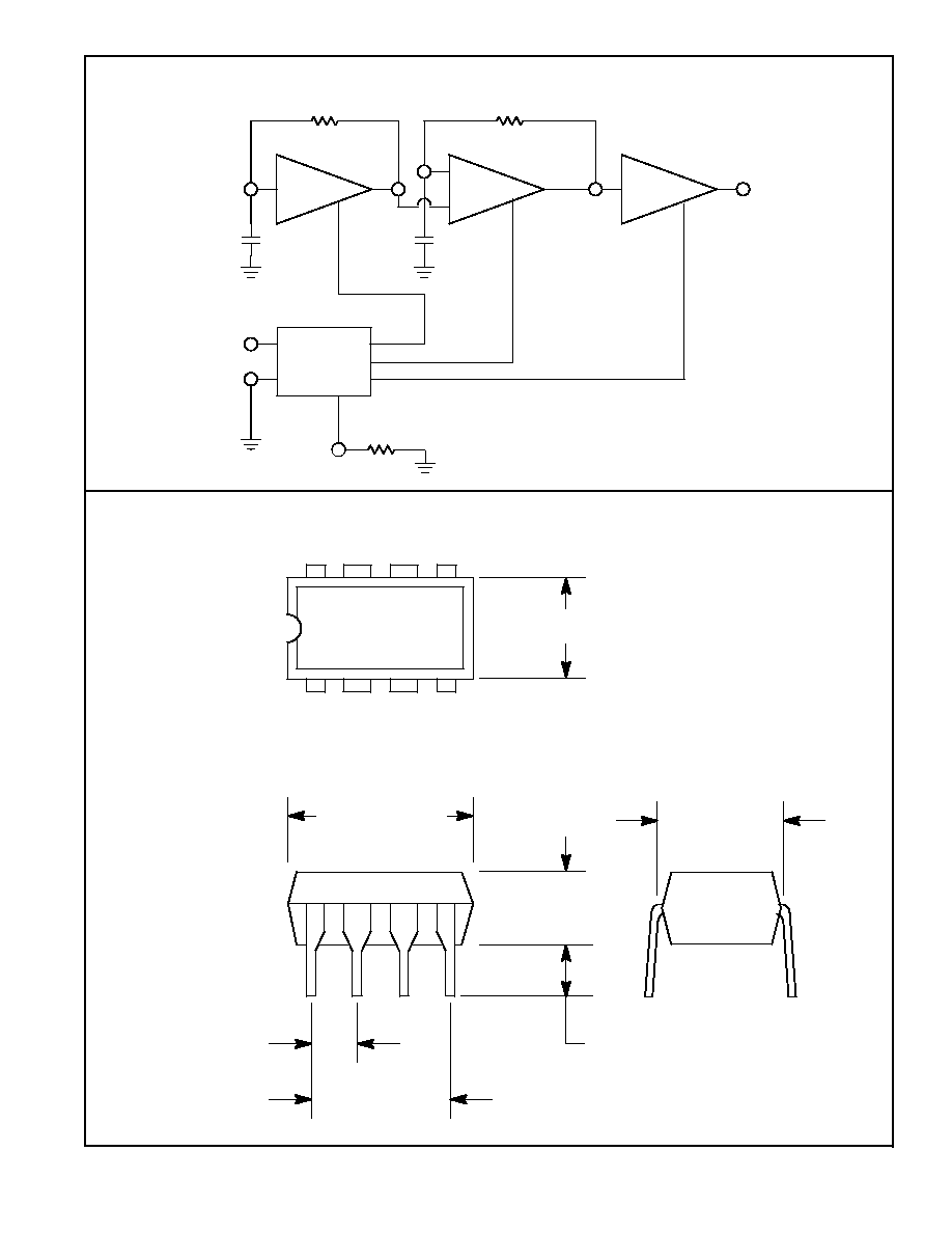
Pin Connection Diagram (NTE1648)
High
Freq
OSC
Amp
Power
Supply
with
Hysteresis
Low
Freq
OSC
Output
Input
Trigger Input
NOTE: C1, C2, R1, and
R2 are external parts
R1
R2
C1
C2
1
2
3
4
5
6
7
8
High
Freq
OSC
Amp
Power
Supply
with
Hysteresis
Low
Freq
OSC
Output
Input
NOTE: C1, C2, R1, R2
and R3 are external
parts
R1
R2
C1
C2
1
3
4
5
6
7
8
Pin Connection Diagram (NTE1649)
Regulated Initiation Current
2
R3
8
5
.256 (6.52) Max
.393 (10.0)
Max
1
4
.300 (7.62)
.300 (7.62)
.150
(3.81)
.070 (1.77) Min
.100 (2.54)