
NTE2078
Integrated Circuit
5≠Stage Darlington Transistor Array
Description:
The NTE2078 is a 5≠channel sink driver consisting of 10 NPN transistors connected to form high current
gain driver pairs.
Features:
D
Output sustaining voltage to 30V
D
High Output Sink Current to 500mA
D
Wide Operating Temperature Range (T
A
= ≠20
∞
to +75
∞
C)
Application:
D
Relay and printer drivers
D
LED or incandescent display digit driver
D
Interface for standard MOS/Bi POLAR logics.
Absolute Maximum Ratings: (T
A
= ≠20
∞
to +75
∞
C, unless otherwise specified)
Output Sustaining Voltage (Transistor OFF), V
CEO
≠0.5 to 30V
. . . . . . . . . . . . . . . . . . . . . . . . . . . . . . .
Collector Current (Transistor ON), I
C
500mA
. . . . . . . . . . . . . . . . . . . . . . . . . . . . . . . . . . . . . . . . . . . . . . .
Power Dissipation (T
A
= +25
∞
C), P
d
1.47W
. . . . . . . . . . . . . . . . . . . . . . . . . . . . . . . . . . . . . . . . . . . . . . . . .
Operating Ambient Temperature Range, T
opr
≠20
∞
to +75
∞
C
. . . . . . . . . . . . . . . . . . . . . . . . . . . . . . . . . .
Storage Temperature Range, T
stg
≠55
∞
to +125
∞
C
. . . . . . . . . . . . . . . . . . . . . . . . . . . . . . . . . . . . . . . . . .
Electrical Characteristics: (T
A
= ≠20
∞
to +75
∞
C, Note 1, unless otherwise specified)
Parameter
Symbol
Test Conditions
Min
Typ Max Unit
Output Sustaining Voltage
V
(BR)CEO
I
CEO
= 100
µ
A
30
≠
≠
V
Output Saturation Voltage
V
CE(sat)
V
I
= 2mA, I
C
= 400mA
≠
1.0
2.4
V
V
I
= 1mA, I
C
= 200mA
≠
0.8
1.6
Input Voltage
V
I
I
I
= 1mA
0.6
1.35
1.7
V
Output Voltage
V
O
0
≠
30
V
Note 1. All typical values are at T
A
= 25
∞
C.
Electrical Characteristics (Cont'd): (T
A
= ≠20
∞
to +75
∞
C, Note 1, unless otherwise specified)
Parameter
Symbol
Test Conditions
Min
Typ Max Unit
Collector Current per Channel
I
C
Percent Duty Cycle: < 10%
0
≠
400
mA
Percent Duty Cycle: < 55%
0
≠
200
"H" Input Current
I
IH
I
C
= 200mA
1
≠
5
mA
I
C
= 400mA
2
≠
5
"L" Input Current
I
IL
≠
0
≠
µ
A
Note 1. All typical values are at T
A
= 25
∞
C.
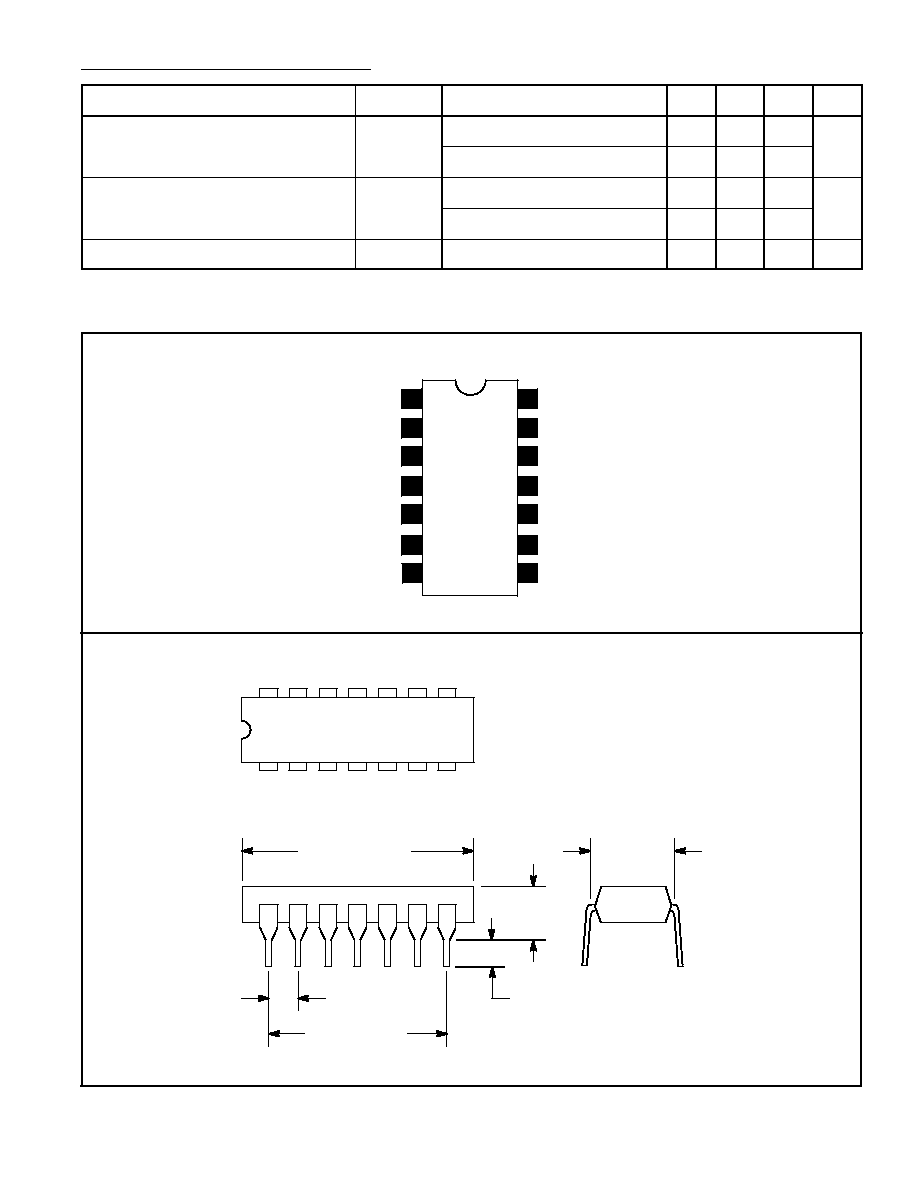
Pin Connection Diagram
Input 4
Output 3
Input 3
Input 2
Input 1
1
2
3
4
N.C.
5
6
Input 5
7
GND
14
13
12
11
N.C.
Output 1
Output 2
10
9
Output 5
8
N.C.
Output 4
.600 (15.24)
1
7
14
8
.300 (7.62)
.200 (5.08)
Max
.100 (2.45)
.099 (2.5) Min
.785 (19.95)
Max