NTE789
Integrated Circuit
Stereo Multiplex Decoder
Description:
The NTE789, a monolithic silicon integrated circuit, is a stereo multiplex decoder intended for FM multiplex
systems.
This stereo multiplex decoder requires only one lowнinductance tuning coil (requires only one adjustment for
complete alignment), provides automatic stereo switching, energizes a stereo indicator lamp, and operates
from a wide range of voltage supplies.
Figure 1 shows the block diagram for the NTE789. The input signal form the detector is amplified by a lowнdis-
tortion preamplifier and simultaneously applied to both signal, generated by a local voltageнcontrolled oscilla-
tor (VCO), is counted down by two frequency dividers to a 38kHz signal and to two 19нkHz pilotнtone supplied
by the FM detector is compared to the locally generated 19нkHz signal in a synchronous detector.
The resultant signal controls the voltage controlled oscillator (VC)) so that it produces an output signal to
phaseнlock the stereo decoder with the pilot tone. A second sychronous detector compares the locally gener-
ated 19нkHz signal with the 19нkHz pilot tone. If the pilot tone exceeds and externally adjustable threshold
voltage, a Schmitt trigger circuit is energized. The signal from the Schmitt trigger lights the stereo indicator,
enables the 38нkHz synchronous detector, and automatically switches the NTE789 form monaural to stereo
operation. The output signal from the 38нkHz detector and the composite signal from the preamplifier are ap-
plied to a matrixing circuit from which emerge the resultant left and right channel audio signals. These signals
are applied to their respective left and right post amplifiers for amplification to a level sufficient to drive most
audio amplifiers.
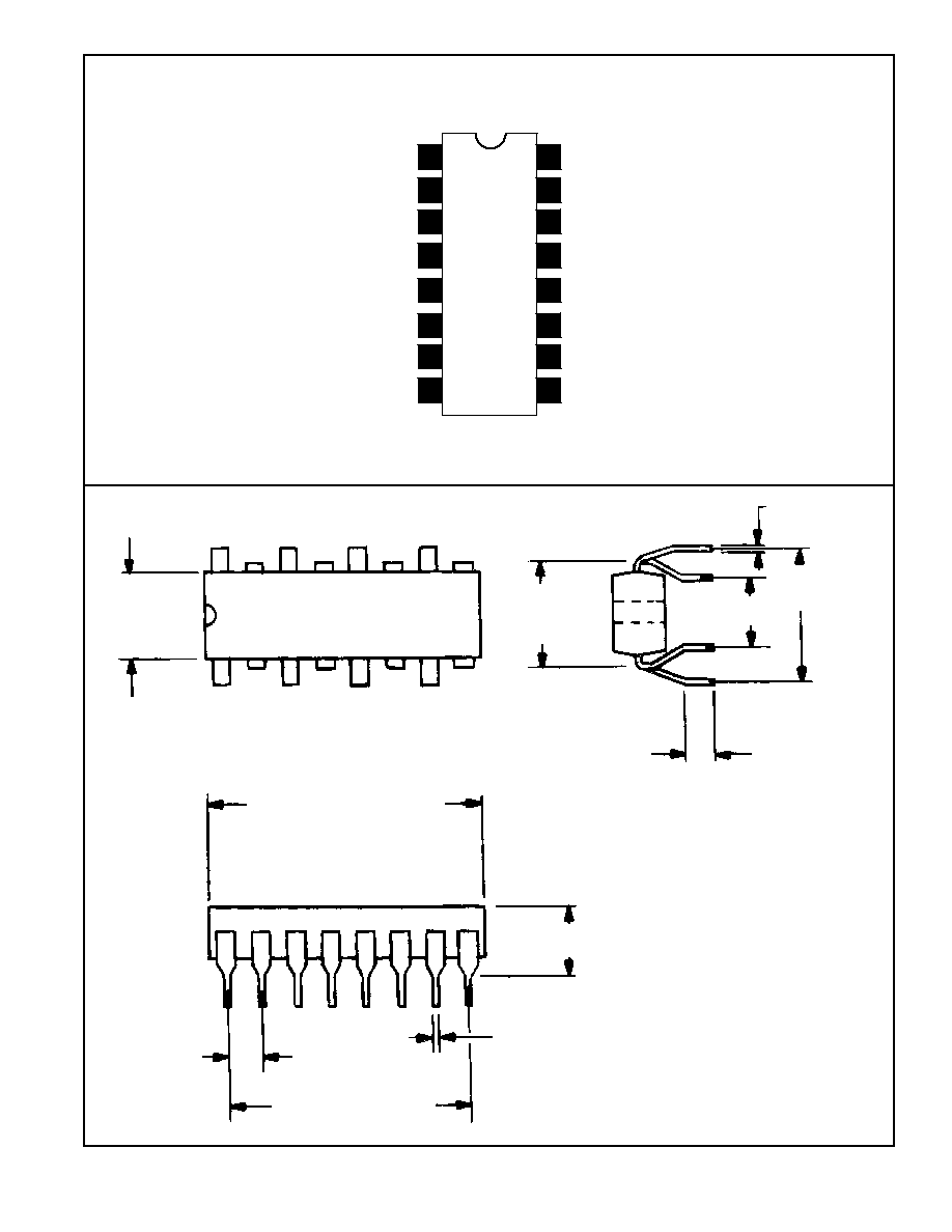
The NTE789 utilizes the 16нlead quadнinнline plastic package and operates over the ambient temperature
range of н40
░
C to +85
░
C.
Features:
D
Requires the use of only one lowнinductance tuning coil
D
Automatic stereo switching
D
Directly drives a stereo indicator lamp up to 100mA
D
Includes driver for stereoнlamp indicator
D
Operates from a wide range of power supplies: 10 to 16 volts
D
Requires only one adjustment for alignment
D
Switching from monaural to stereo and stereo to monaural produces no audible thumps
D
Low distortion: under 0.5%
D
Separate dc input permits stereo defeat or enable
D
High signal output: directly drives audio amplifiers
D
Excellent SCA (storecast) rejection: 55dB typ.
D
High audio channel separation: 40dB typ.
Absolute Maximum Ratings: (T
A
= +25
░
C unless otherwise specified)
DC Supply Voltage
16V
. . . . . . . . . . . . . . . . . . . . . . . . . . . . . . . . . . . . . . . . . . . . . . . . . . . . . . . . . . . . . . . . . . . . . . . . .
Current at Pin12
100mA
. . . . . . . . . . . . . . . . . . . . . . . . . . . . . . . . . . . . . . . . . . . . . . . . . . . . . . . . . . . . . . . . . . . . . . . .
Input Signal Voltage (Composite)(Note 1)
400mV
. . . . . . . . . . . . . . . . . . . . . . . . . . . . . . . . . . . . . . . . . . . . . . . . . .
Operating Ambient Temperature Range
н40 to +85
░
C
. . . . . . . . . . . . . . . . . . . . . . . . . . . . . . . . . . . . . . . . . . . . . . .
Storage Ambient Temperature Range
н65 to +150
░
C
. . . . . . . . . . . . . . . . . . . . . . . . . . . . . . . . . . . . . . . . . . . . . . . .
Lead Temperature (During Soldering, 1/32" (0.79mm) from case,10s max.)
+265
░
C
. . . . . . . . . . . . . . . . . . . . .
Note 1. For stereo operation, a minimum input signal voltage (composite) of 40mV is required.
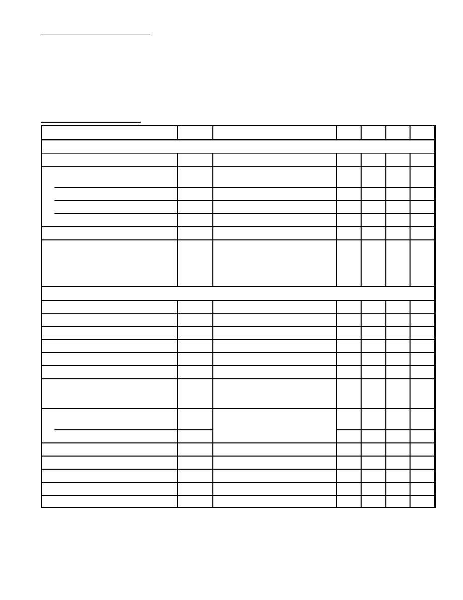
Electrical Characteristics: (T
A
= +25
░
C, V+ = 12 unless otherwise specified)
Parameter
Symbol
Test Conditions
Min
Typ
Max
Unit
Static Characteristics
Total Current (Pin9, Pin10,Pin11)
I
total
Lamp OFF
н
22
27
mA
DC Voltage
Pin1
V
1
1.6
2.3
3.1
V
Pin6 (Indicator Lamp OFF)
V
6
н
2.1
3.6
V
Pin9 and Pin10
V
9
, V
10
3.7
5.4
7.4
V
Pin12 (Indicator Lamp OFF)
V
12
V+ = 16V
12.7
н
н
V
Voltage Differential (Pin2 н Pin1)
V
2
н V
1
н
0
0.1
V
Current at Pin12
(In actual use external circuit
resistance (e.g. lamp should limit
Pin12 to the maximum rated value
of 100mA)
V
IN
(at f = 19kHz) = 18mV
75
100
н
mA
Static Characteristics
Input Impedance
Z
in
н
50k
н
Channel Separatiom (L + R Reference)
V
IN
= 180mV, Note 3
25
40
н
dB
Channel Balance (Monaural)
V
IN
= 180mV
н
0.3
3.0
dB
Monaural Gain
V
IN
= 180mV
3
6
9
dB
Stereo/Monaural Gain Ratio
V
IN
= 180mV, Note 3
н
▒
0.3
▒
3.0
dB
Indicator Lamp н TurnнON Voltage
19kHz pilotнtone at Pin1
н
4
н
mV
Capture Range
(Deviation from 76kHz center
frequency)
19kHz pilotнtone voltage = 18mV
▒
6.6
▒
10
н
%
Distortion (75
╡
s Deнemphasis)
2
nd
Harmonic
V
IN
= 240mV
н
0.2
н
%
3
rd
, 4
th
, and 5
th
Harmonic
н
< 0.1
н
%
19kHz Rejection
н
35
н
dB
38kHz Rejection
н
25
н
dB
SCA (Storecast) Rejection
н
55
н
dB
Stereo Defeat Voltage (V
4
)
н
н
< 0.9
V
Stereo Enable Voltage (V
4
)
> 1.6
н
н
V
Note 2. For improved pilot sensitivity and overload characteristics, replace the .039
╡
F capacitor between Pin7
and Pin8 with a Series LнC Network (L = 4.7mH, C = 0.015
╡
F). Under these conditions, Indicator
Lamp Sensitivity: "ON" = 3.3mV, "OFF" = 2.0mV.
Note 3. For stereo operation, test conditions require a composite stereo input signal (modulated at 1kHz) in-
cluding a 19kHz (18mV) pilotнtone signal.