NTE1491
Integrated Circuit
AM RF/IF Amp
Description:
The NTE1491 is an integrated circuit in a 14≠Lead DIP type package designed for AM/FM receivers.
Features:
D
Low External Parts
D
IF, RF, AGC, in One Single Package
D
Dual AGC Amps
Absolute Maximum Ratings: (T
A
= +25
∞
C unless otherwise specified)
Supply Voltage, V
CC
18V
. . . . . . . . . . . . . . . . . . . . . . . . . . . . . . . . . . . . . . . . . . . . . . . . . . . . . . . . . . . . . . . .
Signal Input Voltage, V
i
7V
p≠p
. . . . . . . . . . . . . . . . . . . . . . . . . . . . . . . . . . . . . . . . . . . . . . . . . . . . . . . . . . .
Total Power Dissipation (T
A
= +75
∞
C), P
D
350mW
. . . . . . . . . . . . . . . . . . . . . . . . . . . . . . . . . . . . . . . . . .
Operating Temperature Range, T
opt
≠20
∞
to +75
∞
C
. . . . . . . . . . . . . . . . . . . . . . . . . . . . . . . . . . . . . . . . . .
Storage Temperature Range, T
stg
≠40
∞
to +125
∞
C
. . . . . . . . . . . . . . . . . . . . . . . . . . . . . . . . . . . . . . . . . .
Recommended Operating Condition: (T
A
= +25
∞
C unless otherwise specified)
Parameter
Symbol
Min
Typ
Max
Unit
Supply Voltage
V
CC
9
13
16
V
Electrical Characteristics: (T
A
= +25
∞
C, V
CC
= 13V, f = 1MHz, f
mod
. = 400Hz, MOD = 30%,
R
L
= 10k
unless otherwise specified)
Parameter
Symbol
Test Conditions
Min
Typ
Max
Unit
Idle Current
I
CC
18
26
34
mA
Maximum Sensitivity
MS
o = 20mV
rms
≠
10
17
dB/
µ
V
Signal Noise
S/N
i = 74dB
µ
V
48
55
≠
dB
Detector Voltage Out
o
i = 74dB
µ
V
40
60
90
mV
rms
Total Harmonic Distortion
THD
i = 126dB
µ
V
≠
0.4
3
%
Tuner Performance: (T
A
= +25
∞
C, V
CC
= 13V, f = 1MHz, f
mod
. = 400Hz, MOD = 30%, R
L
= 10k
unless otherwise specified)
Characteristics
Test Conditions
Typ
Unit
Maximum Sensitivity
o
= 20mV
rms
10
dB
µ
V
Usable Sensitivity (
i
)
S/N = 20dB
24
dB
µ
V
Distortion Output Voltage
i
= 74 dB
µ
V
60
mV
rms
Harmonic Distortion
i
= 74dB
µ
V
0.4
%
S/N Ratio
i
= 74dB
µ
V
55
dB
Total Harmonic Distortion
i
= 126dB
0.4
%
IF Rejection Ratio
f = 1MHz,
o
= 20mV, IF = 450kHz
67
dB
Image Rejection Ratio
f = 1MHz,
o
= 20mV, f + 2 IF
80
dB
Selectivity
f = 1MHz,
f =
±
10kHz
31
dB
AM Whistle Rejection
i
= 74dB
µ
V
2
nd
IF = 900kHz
45
dB
3
rd
IF = 1350kHz
50
dB
V
CC
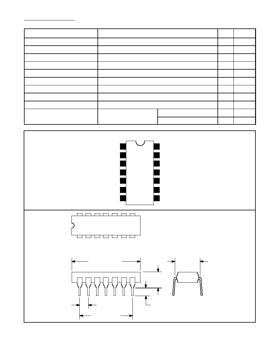
Pin Connection Diagram
1
2
3
4
Mixer Output
IF Input
Bypass
IF Output
5
AGC Input
6
Bypass
7
GND
14
13
12
11
OSC Output
OSC Input
Mixer Input
10
RF Output
9
Bypass
8
RF Input
.600 (15.24)
1
7
14
8
.300
(7.62)
.200 (5.08)
Max
.100 (2.45)
.099 (2.5) Min
.785 (19.95)
Max