 | Электронный компонент: NTE1890 | Скачать:  PDF PDF  ZIP ZIP |

NTE1890
Integrated Circuit
NTSC Decoder for TV
Description:
The NTE1890 is a monolithic integrated decoder for the NTSC color television standards. It combines
all functions required for the demodulation of NTSC signals. Further more it contains a luminance
amplifier, an RGB¡matrix and amplifier. These amplifiers supply output signals up to 5V peak¡to¡
peak (picture information) enabling direct drive of the discrete output stages.
Absolute Maximum Ratings:
Maximum Supply Voltage (Pin1), V
P
= V
1¡23
13.2V
. . . . . . . . . . . . . . . . . . . . . . . . . . . . . . . . . . . . . . . . .
Maximum Total Power Disipation, P
tot
1.7W
. . . . . . . . . . . . . . . . . . . . . . . . . . . . . . . . . . . . . . . . . . . . . . . .
Operating Ambient Temperature Range, T
A
¡25
░
to +65
░
C
. . . . . . . . . . . . . . . . . . . . . . . . . . . . . . . . . . .
Storage Temperature Range, T
stg
¡25
░
to +150
░
C
. . . . . . . . . . . . . . . . . . . . . . . . . . . . . . . . . . . . . . . . . .
Thermal Resistance, Junction¡to¡Ambient, R
thJA
50K/W
. . . . . . . . . . . . . . . . . . . . . . . . . . . . . . . . . . . .
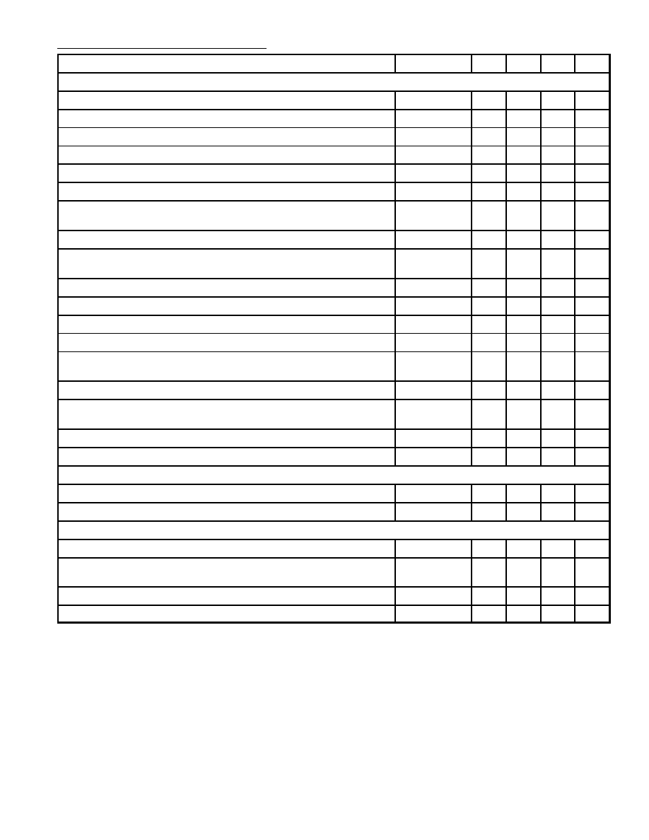
Electrical Characteristics: (V
P
= V
1¡23
= 12V, T
A
= +25
░
C unless otherwise specified)
Parameter
Symbol
Min
Typ
Max
Unit
Supply (Pin1)
Supply Voltage
V
P
= V
1¡23
8.0
12.0
13.2
V
Supply Current
I
P
= I
1
¡
85
¡
mA
Total Power Dissipation
P
tot
¡
1.0
¡
W
Luminance Amplifier (Pin9)
Input Voltage (Peak¡to¡Peak Value, Note 1)
V
9¡23(p¡p)
¡
450
¡
mV
Input Level Before Clipping
V
9¡23
¡
¡
2
V
Input Current
I
9
¡
0.15
1.0
╡
A
Contrast Control Range
¡17
¡
+3
dB
Control Voltage for an Attenuation of 40dB
¡
1.2
¡
V
Input Current Contrast Control
I
7
¡
¡
15
╡
A
Peaking of Luminance Signal
Output Impedance (Pin10)
|Z
10¡23
|
¡
200
¡
Ratio of Internal/External Current when Pin10 is Short¡Circuited
¡
3
¡
Control Voltage for Peaking Adjustment (Pin11)
V
11¡23
¡
2.4
¡
V
Input Impedance (Pin11)
|Z
11¡23
|
¡
10
¡
k
Note 1. Signal with the negative¡going sync; amplitude includes sync amplitude.
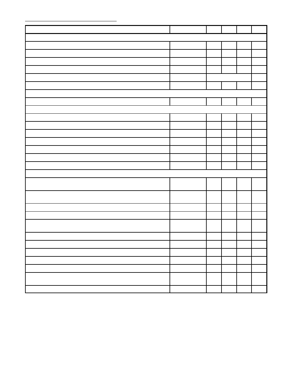
Electrical Characteristics (Cont'd): (V
P
= V
1¡23
= 12V, T
A
= +25
░
C unless otherwise specified)
Parameter
Symbol
Min
Typ
Max
Unit
Chrominance Amplifier (Pin3)
Input Voltage (Peak¡to¡Peak Value, Note 2)
V
3¡23(p¡p)
55
550
1100
mV
Input Impedance
|Z
3¡23
|
¡
8
¡
k
Input Capacitance
C
3¡23
¡
4
6
pF
ACC Control Range
30
¡
¡
dB
Change of the Burst Signal at the Output over the Whole Control Range
¡
¡
1
dB
Gain at Nominal Contrast/Saturation Pin3 to Pin24 (Note 3)
13
¡
¡
dB
Output Voltge (Peak¡to¡Peak Value at Burst Signal of 300mV
(p¡p)
,
(Note 3)
V
24¡23(p¡p)
¡
240
¡
mV
Maximum Output Voltage Range (Pin24, Peak¡to¡Peak Value)
V
24¡24(p¡p)
¡
1.7
¡
V
Distortion of Chrominance Amplifier at V
24¡23(p¡p)
= 0.5V (Output)
up to V
3¡23(p¡p)
= 1V (Input)
d
¡
3.0
5.0
%
Frequency Response Between 0 and 5MHz
24¡3
¡
¡
¡2
dB
Saturation Control Range
50
¡
¡
dB
Input Current Saturation Control (Pin6)
I
6
¡
¡
20
╡
A
Tracking Between Luminance and Chrominance Contrast Control
¡
¡
2
dB
Cross¡Coupling Between Luminance and Chrominance Amplifier
(Note 4)
¡
¡
¡46
dB
Signal¡to¡Noise Ratio at Nominal Input Signal (Note 5)
S/N
56
¡
¡
dB
Phase Shift Between Burst and Chrominance at Nominal
Contrast/Saturation
¡
¡
▒
5
deg
Output Impedance of Chrominance Amplifier
|Z
24¡23
|
¡
25
¡
Output Current
I
24
¡
¡
10
mA
Reference Part (Phase¡Locked Loop)
Catching Range (Note 6)
f
500
700
¡
Hz
Phase Shift for
▒
400Hz Deviation for f
OSC
(Note 6)
¡
¡
5
deg
Reference Part (Oscillator)
Temperature Coefficient of Oscillator Frequency (Note 6)
TC
OSC
¡
¡1.5
¡
Hz/K
Frequency Variation when Supply Voltage Increases from
10V to 13.2V (Note 6)
f
OSC
¡
40
¡
Hz
Input Resistance (Pin22)
R
22¡23
¡
300
¡
Input Capacitance (Pin22)
C
22¡23
¡
¡
10
pF
Note 2. Indicated is a signal for a color bar with 75% saturation; chrominance to burst ratio is 2.2:1.
Note 3. Nominal contrast is specified as the maximum contrast ¡3dB and nominal saturation as the
maximum saturation ¡6dB.
Note 4. Cross coupling is measured under the following conditions:
S
Input signals nominal.
S
Contrast and aturation such that the nominal output signals are obtained.
S
The signals at the output at which no signal should be available must be compared
with the nominal output signal at that output.
Note 5. The signal¡to¡noise ratio is defined as peak¡to¡peak signal with respect to RMS noise.
Note 6. All frequency variations are referred to 3.58MHz carrier frequency.
Electrical Characteristics (Cont'd): (V
P
= V
1¡23
= 12V, T
A
= +25
░
C unless otherwise specified)
Parameter
Symbol
Min
Typ
Max
Unit
Reference Part (ACC Generation, Pin22)
Control Voltage at Nominal Input Signal
V
2¡23
¡
5.3
¡
V
Control Voltage without Chrominance Input
V
2¡23
¡
2.8
¡
V
Color¡Off Voltage
V
2¡23
¡
3.4
¡
V
Color¡On Voltage
V
2¡23
¡
3.6
¡
V
Change in Burst Amplitude with Supply Voltage
Independent
Voltage at Pin4 at Nominal Input Signal
V
4¡23
¡
5.2
¡
V
Reference Part (Hue Control)
Control Range
▒
50
¡
¡
deg
Demodulator Part
Input Burst Signal Amplitude (Peak¡to¡Peak Value, Pin17)
V
17¡23(p¡p)
¡
320
¡
mV
Input Impedance (Pin17, Note 7)
|Z
17¡23
|
¡
2
¡
k
Ratio of Demodulated Signals (B¡Y)/(R¡Y)
V
15¡23
/V
13¡23
¡
1.1
¡
Ratio of Demodulated Signals (G¡Y)/(R¡Y); No (B¡Y) Signal
V
14¡23
/V
13¡23
¡
0.26
¡
Ratio of Demodulated Signals (G¡Y)/(B¡Y); No (R¡Y) Signal
V
14¡23
/V
15¡23
¡
0.22
¡
Frequency Response Between 0 and 1MHz
¡
¡
¡3
dB
Crosstalk Between Color Difference Signals
40
¡
¡
dB
RGB Matrix and Amplifiers
Output Voltage at Nominal Input Signal
(Peak¡to¡Peak value, Black¡to¡White, Note 3)
V
13, 14, 15¡23(p¡p)
¡
5
¡
V
Output Voltage at Pin13 at Nominal Contrast/Saturation and
No Luminance Signal to (R¡Y) (Peak¡to¡Peak Value)
V
13¡23(p¡p)
¡
5.25
¡
V
Maximum Peak¡White Level (Note 8)
V
13, 14, 15¡23
9.0
9.3
9.6
V
Maximum Output Current (Pin13, Pin14, Pin15)
I
13, 14, 15
¡
¡
10
mA
Output Black Level Voltage for a Brightness Control Voltage
at Pin12 of 2V
V
13, 14, 15¡23
¡
2.7
¡
V
Black Level Shift with Vision Contents
¡
¡
40
mV
Brightness Control Input Current
I
12
¡
¡
5
╡
A
Variation of Black Level with Temperature
V/
T
¡
0.35
1.0
mV/K
Variation of Black Level with Contrast
V
¡
10
100
mV
Relative Spread Between the R, G and B Output Signals
¡
¡
10
%
Relative Black¡Level Varition Between the Three Channels During
Variation of Contrast, Brightness and Supply Voltage
¡
0
20
mV
Differential Black¡Level Drift Over a Temperature Range of 40
░
C
¡
0
20
mV
Note 3. Nominal contrast is specified as the maximum contrast ¡3dB and nominal saturation as the
maximum saturation ¡6dB.
Note 7. These signal amplitudes are determined by th ACC circuit of the reference part.
Note 8. If the typical voltage for this white level is exceeded, the output voltage is reduced by dis-
charging the capacitor at Pin7 (contrast control); discharge current is 1.5mA.
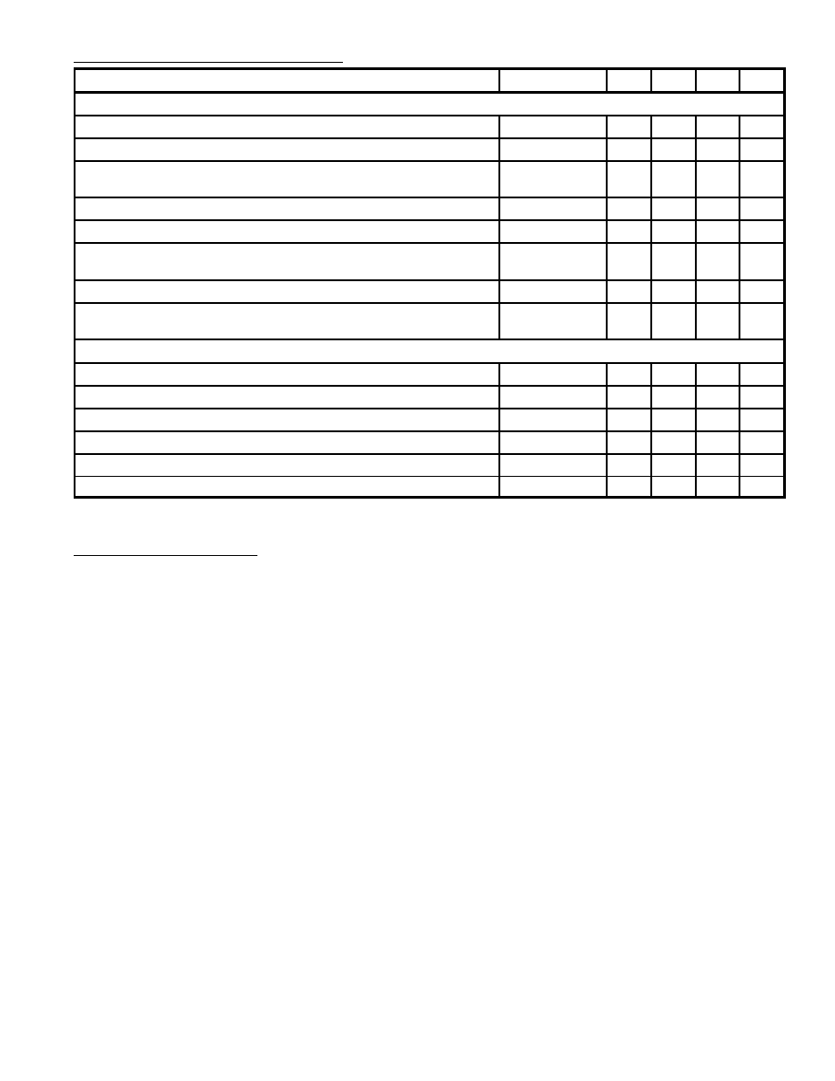
Electrical Characteristics (Cont'd): (V
P
= V
1¡23
= 12V, T
A
= +25
░
C unless otherwise specified)
Parameter
Symbol
Min
Typ
Max
Unit
RGB Matrix and Amplifiers (Cont'd)
Blanking Level at the RGB Outputs
1.9
2.1
2.3
V
Difference in Blanking Level of the Three Channels
¡
0
¡
mV
Differential Drift of the Blanking Levels over a
Temperatue Range of 40
░
C
¡
0
¡
mA
Tracking of Output Black Level with Supply Voltage
¡
1.1
¡
Signal¡to¡Noise Ratio of Output Signals (Note 5)
S/N
62
¡
¡
dB
Residual 7.1MHz Signal and Higher Harmonics at the RGB Outputs
(Peak¡to¡Peak Value)
¡
75
150
mV
Output Impedance of RGB Outputs
|Z
13, 14, 15¡23
|
¡
50
¡
Frequency Response of Total Luminance and RGB Amplifier Circuits
for f = 0 to 5MHz
¡
¡
¡3
dB
Sandcastle Input (PIn8)
Level at which the RGB Blanking is Activated
V
8¡23
1.0
1.5
2.0
V
Level at which Burst Gate and Clamping Pulse are Separated
V
8¡23
6.5
7.0
7.5
V
Delay Bteween Black Level Clamping and Burst Gate Pulse
t
d
¡
0.4
¡
╡
s
Input Current at V
8¡23
= 0 to 1V
¡I
8
¡
¡
1
mA
Input Current at V
8¡23
= 1V to 8.5V
I
8
¡
20
¡
╡
A
Input Current at V
8¡23
= 8.5V to 12V
I
8
¡
¡
2
mA
Note 5. The signal¡to¡noise ratio is defined as peak¡to¡peak signal with respect to RMS noise.
Functional Description:
Luminance Amplifier
The luminance amplifier is voltage driven and requires an input signal of 450mV peak¡to¡peak (posi-
tive video). The luminance delay line must be connected between the IF amplifier and the decoder.
The input signal must be AC coupled to the input Pin9.
The black level at the output of the preamplifier is clamped to a fixed DC level by the black level clamp-
ing circuit. The high input impedance of the luminance amplifier minimizes disturbance of the input
signal black level by the source impedance (delay line matching resistors).
During clamping the low input impedance reduces noise and residual signals. After clamping the sig-
nal is fed to a peaking stage. The overshoot is defined by the capacitor connected to Pin10 and the
peaking is adjusted by the control voltage at Pin11.
The peaking stage is followed by a contrast control stage. The contrast control voltage range (Pin7)
is nominally ¡17 to +3dB.
Chrominance Amplifier
The chrominance amplifier has an asymmetrical input. The input signal must be AC coupled (Pin3)
and have a minimum amplitude of 55mV peak¡to¡peak. The gain control stage has a control range
in excess of 30dB, the maximum input signal should not exceed 1.1V peak¡to¡peak, otherwise clip-
ping of the input signal will occur. From the gain control stage the chrominance signal is fed to the
saturation and contrast control stages. Chrominance and luminance control stages are directly
coupled to obtain good tracking. Saturation is linearly controlled via Pin6. The control voltage range
is 2V to 4V, the input impedance is high and the saturation control range is in excess of 50dB. The
burst signal is not affected by saturation control. The output signal at Pin24 is AC coupled to the demo-
dulators via Pin17.

Functional Description (Cont'd):
Oscillator and ACC Detector
The 7.16MH
Z
reference oscillator operates at twice the subcarrier frequency. The reference signals
for the (R¡Y) and (B¡Y) demodulators, the burst phase detector, and ACC detector are obtained via
the divide¡by¡2 circuit, which provides a 90
░
phase shift. The oscillator is controlled by the burst
phase detector, which is gated with the narrow part of the sandcastle pulse (Pin8). As the burst phase
detector has an asymmetrical output the oscillator can be adjusted by changing the voltage of the out-
put (Pin21) via a high¡ohmic resistor. The capacitor in series with the oscillator crystal must then have
a fixed value. When Pin6 (saturation control) is connected to the positive supply line the burst signal
is suppressed and the color killer is overruled. This position can therefore be used for adjustment of
the oscillator. The adjustment is visible on the screen.
The hue control is obtained by changing the phase of the input signal of the burst phase detector with
respect to the chrominance signal applied to the demodulators. This phase shift is obtained by gener-
ating a 90
░
shift sine¡wave via a Miller integrator (biased via Pin19) which is mixed with the original
burst signal. A control circuit is required in the 90
░
phase shift circuit to make the chrominance voltage
independent of the hue setting. This control circuit is decoupled by a capacitor connected to Pin5.
As the shifted burst signal is synchronously demodulated in a separate ACC detector to generate the
ACC voltage, it is not affected by the hue control. The output pulses of this detector are peak detected
(Pin4) to control the gain of the chrominance amplifier, thus preventing blooming¡up of the color dur-
ing weak signal reception. This ensures reliable operation of the color killer. During color killing the
color channel is blocked by switching¡off saturation control and the demodulators.
Demodulators
The (R¡Y) and (B¡Y) demodulators are driven by the chrominance signal (Pin24) and the reference
signals from the 7.16MH
Z
divider circuit. The phase angle between the two reference carriers is 115
░
.
This is achieved by the (R¡Y) demodulator receiving an additional phase shift by mixing the two sig-
nals from the divider circuit. The phase shift of 115
░
can be varied between 90
░
and 140
░
by changing
the bias voltage at Pin18. The demodulator output signals are fed to R and B matrix circuits and to
the (G¡Y) matrix to provide the (G¡Y) signal which is applied to the G matrix. The demodulator circuits
are killed and blanked by bypassing the input signals.
RGB Matrix and Amplifiers
The three matrix and amplifier circuits are identical and only one circuit will be described. The lumi-
nance and the color difference signals are added in the matrix circuit to obtain the color signal. Output
signals are 5V
(p¡p)
(black¡white) for the following nominal input signals and control settings.
D
Luminance 450mV
(p¡p)
D
Chrominance 550mV
(p¡p)
(burst¡to¡chrominance ratio of the input 1: 2.2)
D
Contrast¡3dB max
D
Saturation¡6dB max
The maximum output voltage is approximately 7V
(p¡p)
. The black level of the blue channel is com-
pared with a variable external reference level (Pin12), which provides the brightness control. The
brightness control range is 1V to 3.2V. The control voltage is stored in a capacitor (connected to
Pin16) and controls the black level at the output (Pin15) between 2V and 4V, via a change of the level
of the luminance signal before matrixing.
Note
Black levels of up to approximately 6V are possible, but amplitude of the output signal is reduced to
3V
(p¡p)
.
If the output signal surpasses the level of 9V the peak¡white limiter circuit becomes active and re-
duces the output signal via the contrast control.