NTE966
Integrated Circuit
3≠Terminal Positive Voltage Regulator, 12V
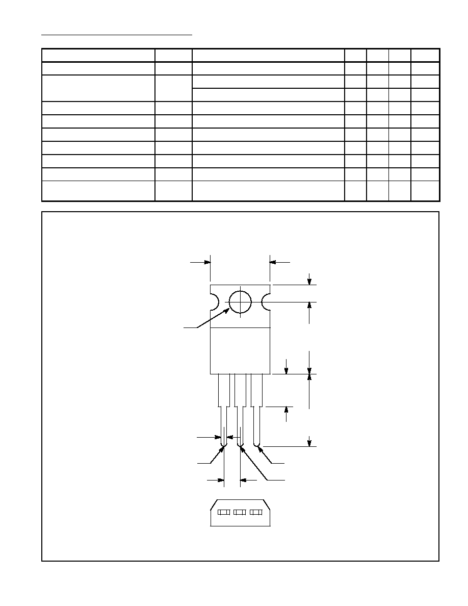
The NTE966 fixed≠voltage regulator is a monolithic integrated circuit in a TO220 type package de-
signed for use in a wide variety of applications including local, on≠card regulation. This regulator em-
ploys internal current limiting, thermal shutdown, and safe≠area compensation. With adequate heat-
sinking it can deliver output currents in excess of 1.0 ampere. Although designed primarily as a fixed
voltage regulator, this device can be used with external components to obtain adjustable voltages and
currents.
Features:
D
Output Current in Excess of 1.0 Ampere
D
No External Components Reguired
D
Internal Thermal Overload Protection
D
Internal Short≠Circuit Current Limiting
D
Output Transistor Safe≠Area Compensation
Absolute Maximum Ratings: (T
A
= +25
∞
C unless otherwise specified)
Input Voltage, V
in
35Vdc
. . . . . . . . . . . . . . . . . . . . . . . . . . . . . . . . . . . . . . . . . . . . . . . . . . . . . . . . . . . . . . . . .
Power Dissipation (T
A
= +25
∞
C), P
D
Internally Limited
. . . . . . . . . . . . . . . . . . . . . . . . . . . . . . . . . . . . . .
Derate above +25
∞
C
15.4mW/
∞
C
. . . . . . . . . . . . . . . . . . . . . . . . . . . . . . . . . . . . . . . . . . . . . . . . . . .
Power Dissipation (T
C
= +25
∞
C), P
D
Internally Limited
. . . . . . . . . . . . . . . . . . . . . . . . . . . . . . . . . . . . . .
Derate above +75
∞
C
200mW/
∞
C
. . . . . . . . . . . . . . . . . . . . . . . . . . . . . . . . . . . . . . . . . . . . . . . . . . . .
Thermal Resistance, Junction≠to≠Ambient, R
thJA
65
∞
C/W
. . . . . . . . . . . . . . . . . . . . . . . . . . . . . . . . . . .
Thermal Resistance, Junction≠to≠Case, R
thJC
5
∞
C/W
. . . . . . . . . . . . . . . . . . . . . . . . . . . . . . . . . . . . . . .
Operating Junction Temperature Range, T
J
≠55
∞
to +150
∞
C
. . . . . . . . . . . . . . . . . . . . . . . . . . . . . . . . . .
Storage Junction Temperature Range, T
stg
≠65
∞
to +150
∞
C
. . . . . . . . . . . . . . . . . . . . . . . . . . . . . . . . . .
Electrical Characteristics: (V
in
= 19V, I
O
= 500mA, T
J
= 0
∞
to +125
∞
C unless otherwise specified)
Parameter
Symbol
Test Conditions
Min
Typ
Max
Unit
Output Voltage
V
O
T
J
= +25
∞
C
11.5
12.0
12.5
V
5mA
I
O
1A, P
O
15W, 14.5V
V
in
27V
11.4
12.0
12.6
V
Line Regulation
Reg
line
T
J
= +25
∞
C, Note 1
14.5V
V
in
20V
≠
13
240
mV
16V
V
in
22V
≠
6
120
mV
Load Regulation
Reg
load
T
J
= +25
∞
C, Note 1
5mA
I
O
1.5A
≠
45
160
mV
250mA
I
O
750mA
≠
16
80
mV
Note 1. Load and line regulation are specified at constant junction temperature. Changes in V
O
due
to heating effects must be taken into account separately. Pulse testing with low duty cycle
is used.