NTE5111A thru NTE5166A
Zener Diode, 5 Watt
±
5% Tolerance
Features:
D
Zener Voltage: 3.3V to 200V
D
High Surge Current Capability
Absolute Maximum Ratings:
DC Power Dissipation (T
L
= +75
∞
C, Lead Length = 3/8"), P
D
5W
. . . . . . . . . . . . . . . . . . . . . . . . . . . . .
Derate Above 75
∞
C
40mW/
∞
C
. . . . . . . . . . . . . . . . . . . . . . . . . . . . . . . . . . . . . . . . . . . . . . . . . . . . . .
Forward Voltage (I
F
= 1A), V
F
1.2V
. . . . . . . . . . . . . . . . . . . . . . . . . . . . . . . . . . . . . . . . . . . . . . . . . . . . . . .
Operating Junction Temperature Range, T
J
≠65
∞
to +200
∞
C
. . . . . . . . . . . . . . . . . . . . . . . . . . . . . . . . . .
Storage Temperature Range, T
stg
≠65
∞
to +200
∞
C
. . . . . . . . . . . . . . . . . . . . . . . . . . . . . . . . . . . . . . . . . .
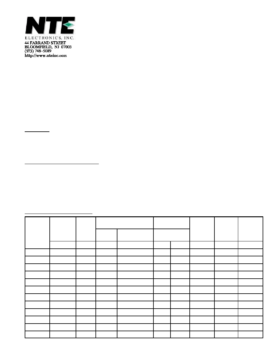
Electrical Characteristics: (T
A
= +25
∞
C unless otherwise specified)
Nominal
Zener
Max Zener Impedance
Max Reverse
Leakage Current
Max Surge
Max
Voltage
Max
Voltage
V
Z
@ I
ZT
(Note 1)
Test
Current
I
ZT
Z
ZT
@ I
ZT
(Note 1)
Z
ZK
@ I
ZK
= 1mA
(Note 1)
I
R
@ V
R
Current
i
r
(Note 2)
Regulation
V
Z
(Note 3)
Regulator
Current
I
ZM
Volts
mA
µ
A
Volts
Amps
Volt
mA
NTE5111A
3.3
380
3.0
400
300
1
20
0.85
1440
NTE5112A
3.6
350
2.5
500
150
1
18.7
0.8
1320
NTE5113A
3.9
320
2
500
50
1
17.6
0.54
1220
NTE5114A
4.3
290
2
500
10
1
16.4
0.49
1100
NTE5115A
4.7
260
2
450
5
1
15.3
0.44
1010
NTE5116A
5.1
240
1.5
400
1
1
14.4
0.39
930
NTE5117A
5.6
220
1
400
1
2
13.4
0.25
865
NTE5118A
6.0
200
1
300
1
3
12.7
0.19
790
NTE5119A
6.2
200
1
200
1
3
12.4
0.1
765
NTE5120A
6.8
175
1
200
10
5.2
11.5
0.15
700
NTE5121A
7.5
175
1.5
200
10
5.7
10.7
0.15
630
NTE5122A
8.2
150
1.5
200
10
6.2
10
0.2
580
Electrical Characteristics (Cont'd): (T
A
= +25
∞
C unless otherwise specified)
Nominal
Zener
Max Zener Impedance
Max Reverse
Leakage Current
Max Surge
Max
Voltage
Max
Voltage
V
Z
@ I
ZT
(Note 1)
Test
Current
I
ZT
Z
ZT
@ I
ZT
(Note1)
Z
ZK
@ I
ZK
= 1mA
(Note 1)
I
R
@ V
R
Current
i
r
(Note 2)
Regulation
V
Z
(Note 3)
Regulator
Current
I
ZM
Volts
mA
µ
A
Volts
Amps
Volt
mA
NTE5159A
130
10
190
1250
0.5
98.8
1.2
2.5
36.6
NTE5160A
140
8
230
1500
0.5
106
1.2
2.5
34
NTE5161A
150
8
330
1500
0.5
114
1.1
3
31.6
NTE5162A
160
8
350
1650
0.5
122
1.1
3
29.4
NTE5163A
170
8
380
1750
0.5
129
1
3
28
NTE5164A
180
5
430
1750
0.5
137
1
4
26.4
NTE5165A
190
5
450
1850
0.5
144
0.9
5
25
NTE5166A
200
5
480
1850
0.5
152
0.9
5
23.6
Note 1 Test conditions for zener voltage and impedance are as follows: I
Z
is applied 40
±
10ms prior
to reading. Mounting contacts are located 3/8" to 1/2" from the inside edge of mounting clips
to the body of the diode (T
A
= +25
∞
C +8
∞
, ≠2
∞
C).
Note 2 Surge current is specified as the maximum allowable peak, non≠recurrent square≠wave cur-
rent with a pulse width, PW, of 8.3ms. Mounting contact located as specified in Note 1.
Note 3 Test conditions for voltage regulation are as follows: V
Z
measurements are made at 10%
and then at 50% of the I
Z
max value listed in the "Electrical Characteristic" table. The test
current time duration for each V
Z
measurement is 40
±
10ms (T
A
= +25
∞
C +8
∞
, ≠2
∞
C). Mount-
ing contact located as specified in Note 1.
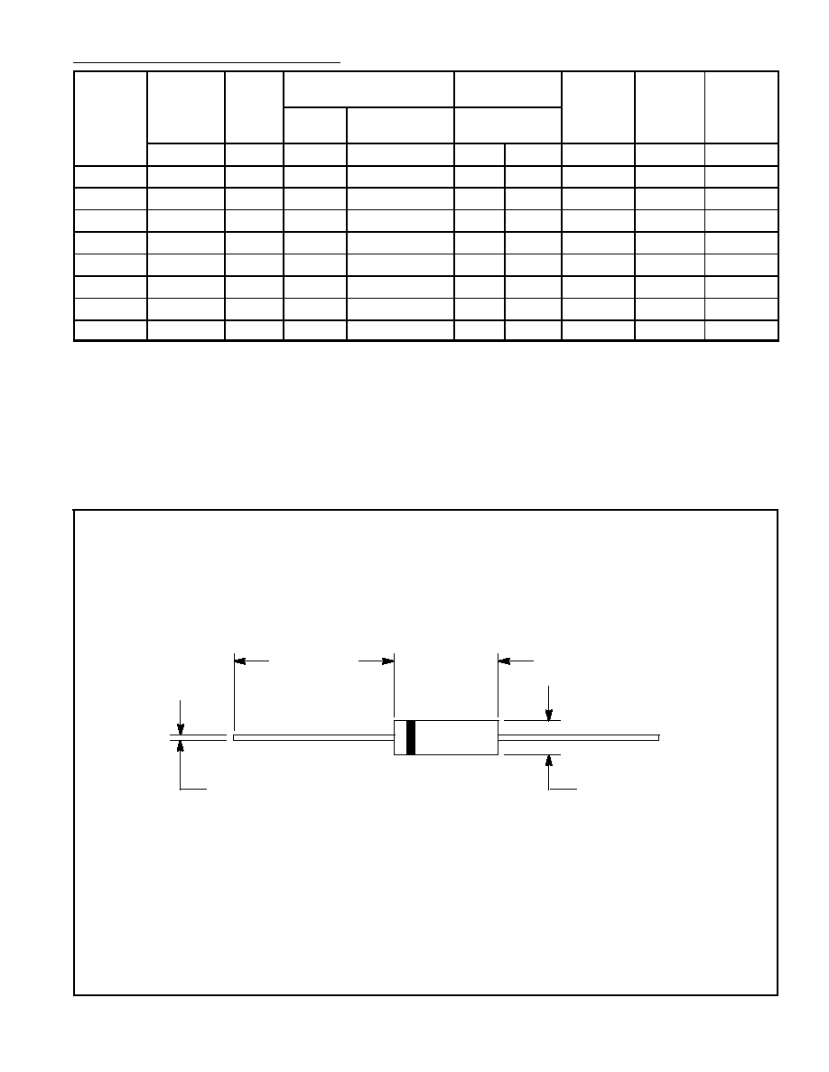
Color Band Denotes Cathode
1.000
(25.4)
.370
(9.41)
.204 (5.19) Dia
.040 (1.02) Dia
