NTE5744 & NTE5745
Powerblock Modules
3 Phase Bride Modules
Description:
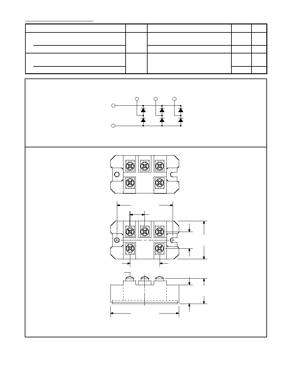
The NTE5744 and NTE5745 powerblock modules are designed for three≠phase full wave rectification
and contain six diodes connected in a three≠phase bridge configuration. The mounting base of the
module is electrically isolated from the semiconductor elements for simple heatsink construction.
Applications:
D
Inverters for AC Motors
D
Power Supply Units for DC Motors
D
DC Power Supply Units for Battery Chargers
D
General Purpose DC Power Supply Units
Absolute Maximum Ratings:
Repetitive Peak Reverse Voltage, V
RRM
NTE5744
800V
. . . . . . . . . . . . . . . . . . . . . . . . . . . . . . . . . . . . . . . . . . . . . . . . . . . . . . . . . . . . . . . . . . .
NTE5745
1600V
. . . . . . . . . . . . . . . . . . . . . . . . . . . . . . . . . . . . . . . . . . . . . . . . . . . . . . . . . . . . . . . . . .
Non≠Repetitive Peak Reverse Voltage, V
RSM
NTE5744
880V
. . . . . . . . . . . . . . . . . . . . . . . . . . . . . . . . . . . . . . . . . . . . . . . . . . . . . . . . . . . . . . . . . . .
NTE5745
1760V
. . . . . . . . . . . . . . . . . . . . . . . . . . . . . . . . . . . . . . . . . . . . . . . . . . . . . . . . . . . . . . . . . .
Average Output Current (50/60Hz, Sinewave), I
D
NTE5744 (T
C
= +103
∞
C)
100A
. . . . . . . . . . . . . . . . . . . . . . . . . . . . . . . . . . . . . . . . . . . . . . . . . . . . .
NTE5745 (T
C
= +97
∞
C)
100A
. . . . . . . . . . . . . . . . . . . . . . . . . . . . . . . . . . . . . . . . . . . . . . . . . . . . . .
Surge Forward Current (Rated Load Conditions), I
FSM
1200A
. . . . . . . . . . . . . . . . . . . . . . . . . . . . . . . .
Maximum I
2
t for Fusing (Rated Load Conditions), I
2
t
6000A
2
sec
. . . . . . . . . . . . . . . . . . . . . . . . . . . . . .
Operating Junction Temperature Range, T
J
≠40
∞
to +150
∞
C
. . . . . . . . . . . . . . . . . . . . . . . . . . . . . . . . . .
Storage Temperature Range, T
stg
≠40
∞
to +125
∞
C
. . . . . . . . . . . . . . . . . . . . . . . . . . . . . . . . . . . . . . . . . .
Isolation Breakdown Voltage (RMS, Main Terminal to Case, 1sec), V
ISO
2500V
. . . . . . . . . . . . . . . . .
Thermal Resistance, Junction≠to≠Case, R
thJC
(50/60Hz Sinewave, Thermal Resistance for Total Loss)
0.22
∞
C/W
. . . . . . . . . . . . . . . . . . . . . .
Thermal Resistance (With Thermal Compound), R
thCF
0.06
∞
C/W
. . . . . . . . . . . . . . . . . . . . . . . . . . . . .