
NTE5926, NTE5927,
NTE6020 thru NTE6045
Industrial Silicon Rectifier, 60A
Features:
D
Low Leakage Current
D
Good Surge Capability up to 1000A
D
Availavle in Standard and Reverse Polarity
Absolute Maximum Ratings: (T
J
= ≠65
∞
C to +175
∞
C)
Maximum Repetitive Peak Reverse Voltage, V
RRM
NTE6020, NTE6021*
50V
. . . . . . . . . . . . . . . . . . . . . . . . . . . . . . . . . . . . . . . . . . . . . . . . . . . . . . . . .
NTE6022, NTE6023*
100V
. . . . . . . . . . . . . . . . . . . . . . . . . . . . . . . . . . . . . . . . . . . . . . . . . . . . . . . .
NTE6026, NTE6027*
200V
. . . . . . . . . . . . . . . . . . . . . . . . . . . . . . . . . . . . . . . . . . . . . . . . . . . . . . . .
NTE6030, NTE6031*
300V
. . . . . . . . . . . . . . . . . . . . . . . . . . . . . . . . . . . . . . . . . . . . . . . . . . . . . . . .
NTE6034, NTE6035*
400V
. . . . . . . . . . . . . . . . . . . . . . . . . . . . . . . . . . . . . . . . . . . . . . . . . . . . . . . .
NTE6038, NTE6039*
500V
. . . . . . . . . . . . . . . . . . . . . . . . . . . . . . . . . . . . . . . . . . . . . . . . . . . . . . . .
NTE6040, NTE6041*
600V
. . . . . . . . . . . . . . . . . . . . . . . . . . . . . . . . . . . . . . . . . . . . . . . . . . . . . . . .
NTE6042, NTE6043*
800V
. . . . . . . . . . . . . . . . . . . . . . . . . . . . . . . . . . . . . . . . . . . . . . . . . . . . . . . .
NTE6044, NTE6045*
1000V
. . . . . . . . . . . . . . . . . . . . . . . . . . . . . . . . . . . . . . . . . . . . . . . . . . . . . . .
NTE5926, NTE5927*
1200V
. . . . . . . . . . . . . . . . . . . . . . . . . . . . . . . . . . . . . . . . . . . . . . . . . . . . . . .
Maximum Direct Reverse Voltage, V
R
NTE6020, NTE6021*
40V
. . . . . . . . . . . . . . . . . . . . . . . . . . . . . . . . . . . . . . . . . . . . . . . . . . . . . . . . .
NTE6022, NTE6023*
80V
. . . . . . . . . . . . . . . . . . . . . . . . . . . . . . . . . . . . . . . . . . . . . . . . . . . . . . . . .
NTE6026, NTE6027*
160V
. . . . . . . . . . . . . . . . . . . . . . . . . . . . . . . . . . . . . . . . . . . . . . . . . . . . . . . .
NTE6030, NTE6031*
240V
. . . . . . . . . . . . . . . . . . . . . . . . . . . . . . . . . . . . . . . . . . . . . . . . . . . . . . . .
NTE6034, NTE6035*
320V
. . . . . . . . . . . . . . . . . . . . . . . . . . . . . . . . . . . . . . . . . . . . . . . . . . . . . . . .
NTE6038, NTE6039*
400V
. . . . . . . . . . . . . . . . . . . . . . . . . . . . . . . . . . . . . . . . . . . . . . . . . . . . . . . .
NTE6040, NTE6041*
480V
. . . . . . . . . . . . . . . . . . . . . . . . . . . . . . . . . . . . . . . . . . . . . . . . . . . . . . . .
NTE6042, NTE6043*
800V
. . . . . . . . . . . . . . . . . . . . . . . . . . . . . . . . . . . . . . . . . . . . . . . . . . . . . . . .
NTE6044, NTE6045*
1000V
. . . . . . . . . . . . . . . . . . . . . . . . . . . . . . . . . . . . . . . . . . . . . . . . . . . . . . .
NTE5926, NTE5927*
1200V
. . . . . . . . . . . . . . . . . . . . . . . . . . . . . . . . . . . . . . . . . . . . . . . . . . . . . . .
Maximum Operating Junction Temperature Range, T
J
≠65
∞
to +175
∞
C
. . . . . . . . . . . . . . . . . . . . . . . . .
Maximum Storage Temperature Range, T
stg
≠65
∞
to +200
∞
C
. . . . . . . . . . . . . . . . . . . . . . . . . . . . . . . . .
Maximum Internal Thermal Resistance, Junction≠to≠Case (DC operation), R
thJC
0.65
∞
C/W
. . . . . .
Thermal Resistance, Case≠to≠Sink (Mounting surface flat, smooth, and greased), R
thCS
0.25
∞
C/W
Mounting Torque, T
Minimum
2.3 (20) N
m (lbf≠in)
. . . . . . . . . . . . . . . . . . . . . . . . . . . . . . . . . . . . . . . . . . . . . . . . . . . . .
Maximum
3.4 (30) N
m (lbf≠in)
. . . . . . . . . . . . . . . . . . . . . . . . . . . . . . . . . . . . . . . . . . . . . . . . . . . .
Approximate Weight, wt
17 (0.6) g (oz)
. . . . . . . . . . . . . . . . . . . . . . . . . . . . . . . . . . . . . . . . . . . . . . . . . . . .
Note 1. * Indicates Anode to Case Polarity
Electrical Characteristics:
Parameter
Symbol
Test Conditions
Rating
Unit
Maximum Average Forward Current
I
F(AV)
T
C
= +115
∞
C, 1≠phase operation, 180
∞
condition
60
A
Maximum Peak One≠Cycle
Non≠Repetitive Surge Current
I
FSM
Half cycle 50Hz sine wave
or 6ms rectangle pulse
Following any rated
load condition and
670
A
Half cycle 60Hz sine wave
or 5ms rectangle pulse
with rated V
RRM
applied
700
A
Half cycle 50Hz sine wave
or 6ms rectangle pulse
Following any rated
load condition and
795
A
Half cycle 60Hz sine wave
or 5ms rectangle pulse
with rated V
RRM
applied following
surge = 0
830
A
Maximum I
2
t for Fusing
I
2
t
t = 10ms
With rated V
RRM
applied following
2250
A
2
s
t = 8.3ms
surge, initial T
J
= T
J
max
2050
A
2
s
Maximum I
2
t for Individual Device
t = 10ms
With V
RRM
= 0 following surge,
3150
A
2
s
Fusing
t = 8.3ms
initial T
J
= T
J
max
2900
A
2
s
Maximum I
2
t for Individual Device
Fusing
I
2
t
t = 0.1 to 10ms, V
RRM
= 0 following surge, Note 2
31,500
A
2
s
Maximum Peak Forward Voltage
V
FM
I
F(AV)
= 60A (188A peak), T
C
= 115
∞
C
1.4
V
Maximum Average Reverse Current
I
R(AV)
Maximum rated I
F(AV)
and V
RRM
, T
C
= 115
∞
C
10
mA
Note 2. I
2
t for time t
x
= I
2
t
t
x
.
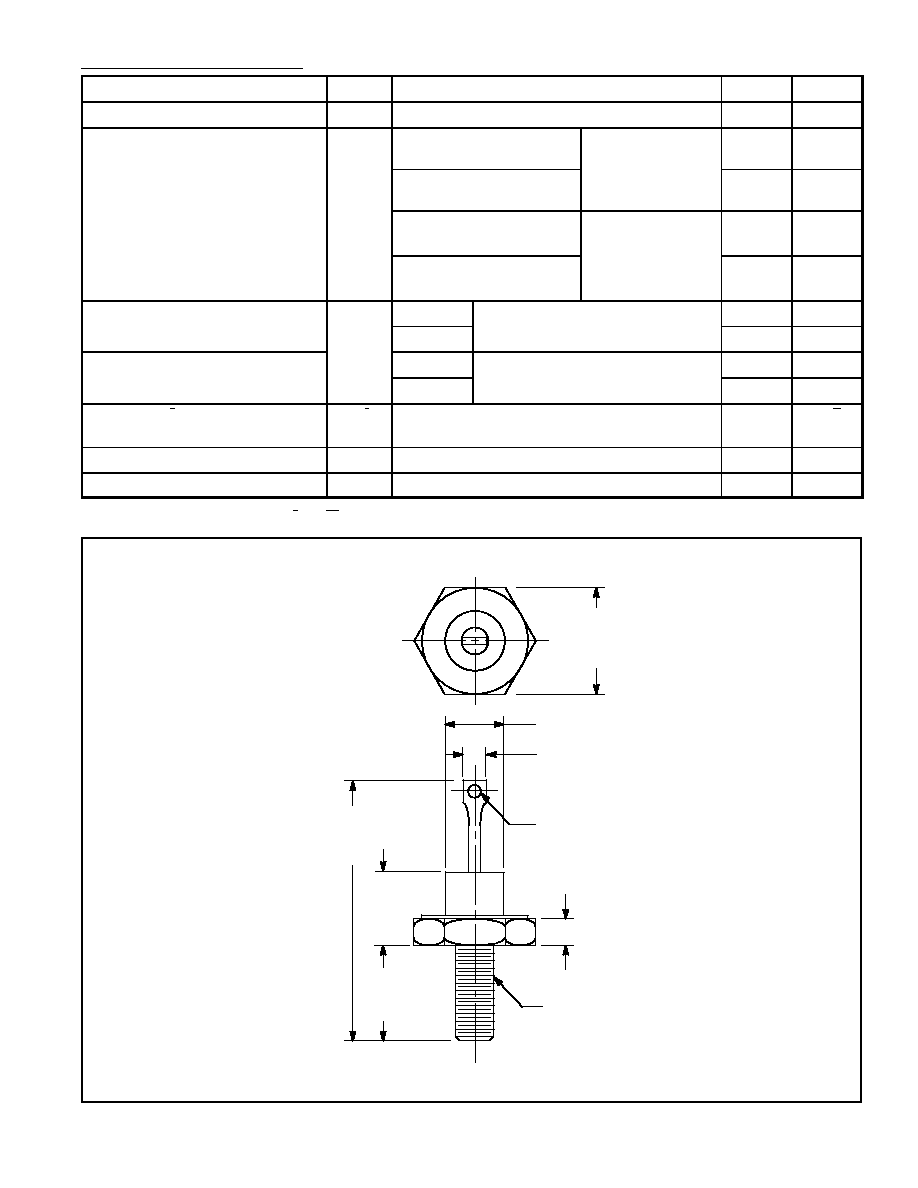
.687
(17.4)
Max
.453
(11.5)
Max
1.288
(32.71)
Max
.450
(11.4)
Max
.200 (5.08) Max
1/4≠28 UNF≠2A
.140 (3.65) Dia Max
.667 (16.9) Dia Max
.375 (9.55) Max