
NTE6106 & NTE6107
Industrial Rectifier, 450A
Features:
D
Standard and Reverse Polarities
D
Flag Lead and Stud Top Terminals
D
High Surge Current Ratings
D
High Rated Blocking Voltages
Applications:
D
Welders
D
Battery Chargers
D
Electrochemical Refining
D
Metal Reduction
D
General Industrial High Current Rectification
Electrical Characteristics:
Voltage (Blocking State Maximums at Maximum T
J
)
Repetitive Peak Reverse Voltage, V
RRM
NTE6106, NTE6107*
1600V
. . . . . . . . . . . . . . . . . . . . . . . . . . . . . . . . . . . . . . . . . . . . . . . . . . . . . . .
Non - Repetitive Transient Peak Reverse Voltage (t
5.0ms), V
RSM
NTE6106, NTE6107*
1800V
. . . . . . . . . . . . . . . . . . . . . . . . . . . . . . . . . . . . . . . . . . . . . . . . . . . . . . .
Reverse Leakage Current (Peak), I
RRM
50mA
. . . . . . . . . . . . . . . . . . . . . . . . . . . . . . . . . . . . . . . . . . . . .
Current (Conducting State Maximums)
RMS Forward Current, I
F (RMS)
700A
. . . . . . . . . . . . . . . . . . . . . . . . . . . . . . . . . . . . . . . . . . . . . . . . . . . . . .
Average Forward Current, I
F (AV)
450A
. . . . . . . . . . . . . . . . . . . . . . . . . . . . . . . . . . . . . . . . . . . . . . . . . . . .
Surge Current, I
FSM
1
/
2
Cycle
8500A
. . . . . . . . . . . . . . . . . . . . . . . . . . . . . . . . . . . . . . . . . . . . . . . . . . . . . . . . . . . . . . . . . .
3 Cycle
6400A
. . . . . . . . . . . . . . . . . . . . . . . . . . . . . . . . . . . . . . . . . . . . . . . . . . . . . . . . . . . . . . . . . . .
10 Cycle
5100A
. . . . . . . . . . . . . . . . . . . . . . . . . . . . . . . . . . . . . . . . . . . . . . . . . . . . . . . . . . . . . . . . . .
Forward Voltage Drop, V
FM
(I
FM
= 1500A, T
J
= +25
∞
C)
1.6V
. . . . . . . . . . . . . . . . . . . . . . . . . . . . . . . . . . . . . . . . . . . . . . . . . . . .
I
2
t for Fusing (for times = 8.3ms), I
2
t
266,000A
2
sec
. . . . . . . . . . . . . . . . . . . . . . . . . . . . . . . . . . . . . . . . .
Note 1. * Indicates reverse (anode to case) polarity.
Electrical Characteristics (Cont'd):
Switching
Typical Reverse Recovery Time, t
rr
(I
FM
= 1500A, t
P
= 190
µ
s, diR/dt = 25A/
µ
s, T
C
= +25
∞
C)
11
µ
s
. . . . . . . . . . . . . . . . . . . . . . . . . .
Thermal and Mechanical
Operating Junction Temperature Range, T
J
- 65
∞
to +175
∞
C
. . . . . . . . . . . . . . . . . . . . . . . . . . . . . . . . . .
Storage Temperature Range, T
stg
- 65
∞
to +200
∞
C
. . . . . . . . . . . . . . . . . . . . . . . . . . . . . . . . . . . . . . . . . .
Thermal Resistance, Junction - to - Case, R
thJC
0.12
∞
C/W
. . . . . . . . . . . . . . . . . . . . . . . . . . . . . . . . . . . .
Thermal Resistance, Case - to - Sink (Lubricated), R
thCS
0.04
∞
C/W
. . . . . . . . . . . . . . . . . . . . . . . . . . . .
Maximum Mounting Torque
360in. lb.
. . . . . . . . . . . . . . . . . . . . . . . . . . . . . . . . . . . . . . . . . . . . . . . . . . . . .
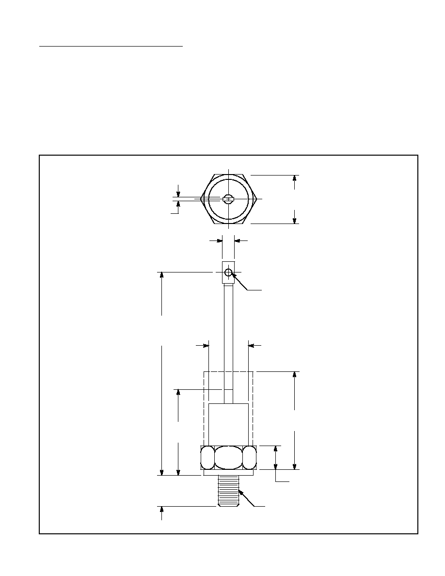
3/4 - 16 UNF - 2A
.340 (8.63) Dia
…
…
…
…
…
…
…
…
…
…
1.490 (37.84) Dia
.620 (15.74)
.643 (16.35)
.118 (3.0)
1.060
(26.92)
1.685
(42.8)
3.100
(78.74)
4.000
(101.6)
10.000
(254.0)
Max