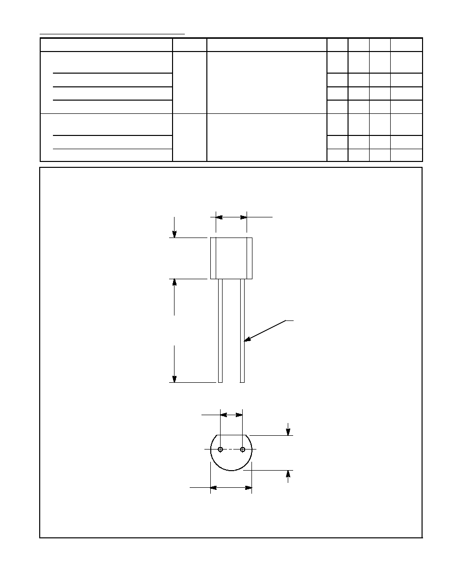
NTE610 thru NTE614
Voltage Variable Capacitance Diode
(Tuning Diode)
Description:
These diodes are designed for high volume requirements of FM Radio and TV tuning and AFC, gener-
al frequency control and tuning applications; providing solid≠state reliability in replacement of me-
chanical tuning methods.
Features:
D
High Q with Guaranteed Minimum Values
D
Controlled and Uniform Tuning Ratio
D
Standard Capacitance Tolerance ≠ 10%
Absolute Maximum Ratings:
Reverse Voltage, V
R
30V
. . . . . . . . . . . . . . . . . . . . . . . . . . . . . . . . . . . . . . . . . . . . . . . . . . . . . . . . . . . . . . . .
Forward Current, I
F
200mA
. . . . . . . . . . . . . . . . . . . . . . . . . . . . . . . . . . . . . . . . . . . . . . . . . . . . . . . . . . . . . .
Device Dissipation (T
A
= 25
∞
C), P
D
280mW
. . . . . . . . . . . . . . . . . . . . . . . . . . . . . . . . . . . . . . . . . . . . . . . .
Derate Above 25
∞
C
2.8mW/
∞
C
. . . . . . . . . . . . . . . . . . . . . . . . . . . . . . . . . . . . . . . . . . . . . . . . . . . . .
Note 1. The NTE611 & NTE612 are discontinued devices and no longer available.
Electrical Characteristics: (T
A
= +25
∞
C unless otherwise specified)
Parameter
Symbol
Test Conditions
Min Typ Max
Unit
Reverse Breakdown Voltage
V
(BR)R
I
R
= 10
µ
A
30
≠
≠
V
Reverse Voltatge Leakage Current
I
R
V
R
= 25V, T
A
= +25
∞
C
≠
≠
0.1
µ
A
Series Inductance
L
S
f = 250MHz, Lead Length
1/16"
≠
6
≠
nH
Case Capacitance
C
C
f = 1MHz, Lead Length
1/16"
≠
0.18
≠
pF
Diode Capacitance Temperature
Coefficient
TC
C
V
R
= 4V, f = 1MHz
≠
280
400 ppm/
∞
C
Diode Capacitance
NTE610
C
T
V
R
= 4V, f = 1MHz
6.1
6.8
7.5
pF
NTE611
9.0
10.0 11.0
pF
NTE612
10.8 12.0 13.2
pF
NTE613
19.8 22.0 24.2
pF
NTE614
29.7 33.0 36.3
pF