
NTE715
Integrated Circuit
TV Chroma IF Amp
Description:
The NTE715 is a combined two≠stage chroma amplifier and functional control circuit. The input signal
is received from the video amplifier and applied to Pin2 of the input amplifier stage. The first amplifier
stage is part of the ACC system and is controlled by differential adjustment from the ACC input Pin1
and Pin14. The output of the 1
st
amplifier is directed to Pin6 from where the signal may be applied
to the ACC detection system of the NTE714 or an equivalent circuit. The output at Pin6 is also applied
to Pin7 which is the input to the 2
nd
amplifier stage. Another output of the 1
st
amplifier at Pin13 is
directed to the killer adjustment circuit.
The DC voltage level at Pin13 rises as the ACC differential voltage decreases with a reduction in the
burst amplitude. At a pre≠set conditions determined by the killer adjustment resistor the killercircuit
is activated and causes the 2
nd
chroma amplifier stage to be cut off. The 2
nd
chroma amplifier stage
is also gain controlled by the adjustment of DC voltage at Pin10. The output of the 2
nd
chroma amplifi-
er stage is available at Pin9. Both amplifier outputs utilize emitter≠followers with short≠circuit protec-
tion.
Absolute Maximum Ratings: (T
A
= +25
∞
C unless otherwise specified)
DC Supply Voltage (Pin8 to Pin4)
30V
. . . . . . . . . . . . . . . . . . . . . . . . . . . . . . . . . . . . . . . . . . . . . . . . . . . .
Device Dissipation (Up to T
A
= +70
∞
C), P
D
530mW
. . . . . . . . . . . . . . . . . . . . . . . . . . . . . . . . . . . . . . . . .
Derate Above 70
∞
C
6.7mW/
∞
C
. . . . . . . . . . . . . . . . . . . . . . . . . . . . . . . . . . . . . . . . . . . . . . . . . . . . .
Operating Ambient Temperature Range, T
opr
≠40
∞
to +85
∞
C
. . . . . . . . . . . . . . . . . . . . . . . . . . . . . . . . . .
Storage Temperature Range, T
stg
≠65
∞
to +150
∞
C
. . . . . . . . . . . . . . . . . . . . . . . . . . . . . . . . . . . . . . . . . .
Lead Temperature (During Soldering, 1/32" (3.17mm) from seating plane, 10s max), T
L
+265
∞
C
. .
Electrical Characteristics: (T
A
= +25
∞
C unless otherwise specified)
Parameter
Symbol
Test Conditions
Min
Typ
Max
Unit
Static Characteristics
Voltages Bias Reference Terminal
V
12
S
1
Open, S
2
Open
≠
17.3
≠
V
Amplifier No. 1 Chroma Input
V
2
S
1
Open, S
2
Open
≠
1.75
≠
V
Amplifier No. 1 Chroma Output
Balanced
V
6
S
1
Open, S
2
Open
≠
20
≠
V
Unbalanced
S
1
Open, S
2
Closed
≠
13.5
≠
V
Amplifier No 2 Chroma Input
V
7
S
1
Open, S
2
Open
≠
1.5
≠
V
Amplifier No 2 Chroma Output
V
9
S
1
Closed, S
2
Open
≠
20.6
≠
V
Supply Current
I
T
S
1
Open, S
2
Open
17
24.5
31
mA
Electrical Characteristics: (T
A
= +25
∞
C unless otherwise specified)
Parameter
Symbol
Test Conditions
Min
Typ
Max
Unit
Dynamic Characteristics
Amplifier No. 1 Voltage Gain
A
V1
E
g
= 30mV
RMS
Measure V
6
14
≠
≠
dB
Amplifier No. 2 Voltage Gain
A
V2
V
g
= 1.0V(RMS) Measure V
7
≠
14
≠
dB
Maximum Chroma Output Voltage
V
9
≠
2
≠
V
RMS
10% Chroma Gain Control Reference Voltage
V
8
≠V
10
E
g
= 50mV
rms
, adjust Chroma
Gain Control to Change V
g
to
10% of Maximum Chroma
Output
2.1
3.8
6.8
V
Output Voltage, Killer Off
V
9
S
1
in Position 2, E
g
= 50mV
RMS
,
adjust "Killer Adjust" for an
abrupt decrease in V
9
≠
≠
12
mV
RMS
Output Voltage, Chroma
V
9
E
g
= 50mV
RMS
, adjust Chroma
control to min. Chroma Output
≠
≠
12
mV
RMS
Bandwidth
Amplifier No. 1
BW
≠
12
≠
MHz
Amplifier No. 2
≠
30
≠
MHz
Amplifier No. 1 Input Impedance
r
I
1
≠
2
≠
k
Amplifier No. 1 Input Capacitance
c
i
1
≠
4
≠
pF
Amplifier No. 1 Output Impedance
r
o
1
≠
85
≠
Ampl. No. 2 Input Impedance
r
i
2
≠
2.1
≠
k
Ampl. No. 2 Output Impedance
r
o
2
≠
85
≠
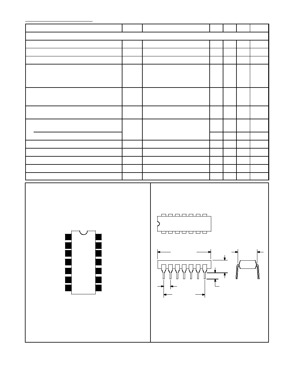
V
CC
Killer Adjust
1
2
3
4
ACC Input
Chroma 1 Input
Gain Preselect
GND
5
N.C.
6
Chroma 1 Output
7
Chroma 2 Input
14
13
12
11
ACC Input
Decouple
Decouple
10
Chroma Level Control
9
Chroma 2 Output
8
.600
(15.24)
1
7
14
8
.300
(7.62)
.200 (5.08)
Max
.100 (2.45)
.099 (2.5) Min
.785 (19.95)
Max
Pin Connection Diagram