NTE2408
Silicon NPN Transistor
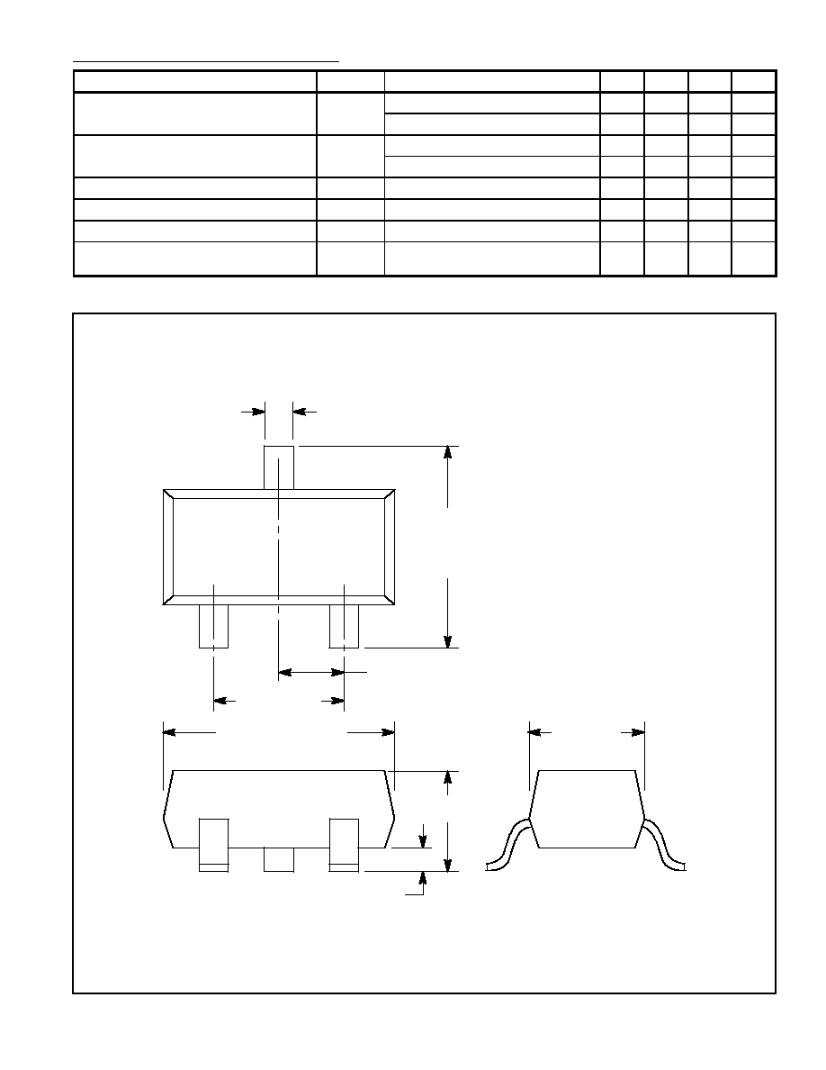
General Purpose Amp, Surface Mount
(Compl to NTE2409)
Description:
The NTE2408 is a silicon NPN general purpose transistor in a SOT≠23 type surface mount package
designed for use in driver stages of audio amplifiers in thick and thin≠film hybrid circuits.
Absolute Maximum Ratings:
Collector≠Base Voltage, V
CBO
80V
. . . . . . . . . . . . . . . . . . . . . . . . . . . . . . . . . . . . . . . . . . . . . . . . . . . . . . .
Collector≠Emitter Voltage, V
CES
80V
. . . . . . . . . . . . . . . . . . . . . . . . . . . . . . . . . . . . . . . . . . . . . . . . . . . . . .
Collector≠Emitter Voltage, V
CEO
65V
. . . . . . . . . . . . . . . . . . . . . . . . . . . . . . . . . . . . . . . . . . . . . . . . . . . . . .
Emitter≠Base Voltage, V
EBO
6V
. . . . . . . . . . . . . . . . . . . . . . . . . . . . . . . . . . . . . . . . . . . . . . . . . . . . . . . . . .
Collector Current, I
C
Continuous
100mA
. . . . . . . . . . . . . . . . . . . . . . . . . . . . . . . . . . . . . . . . . . . . . . . . . . . . . . . . . . . . . . .
Peak
200mA
. . . . . . . . . . . . . . . . . . . . . . . . . . . . . . . . . . . . . . . . . . . . . . . . . . . . . . . . . . . . . . . . . . . .
Peak Emitter Current, I
EM
200mA
. . . . . . . . . . . . . . . . . . . . . . . . . . . . . . . . . . . . . . . . . . . . . . . . . . . . . . . .
Peak Base Current, I
BM
200mA
. . . . . . . . . . . . . . . . . . . . . . . . . . . . . . . . . . . . . . . . . . . . . . . . . . . . . . . . . .
Total Power Dissipation (T
A
= +60
∞
C, Note 1), P
tot
200mW
. . . . . . . . . . . . . . . . . . . . . . . . . . . . . . . . . .
Junction Temperature, T
J
+150
∞
C
. . . . . . . . . . . . . . . . . . . . . . . . . . . . . . . . . . . . . . . . . . . . . . . . . . . . . . . . .
Storage Temperature Range, T
stg
≠65
∞
to +150
∞
C
. . . . . . . . . . . . . . . . . . . . . . . . . . . . . . . . . . . . . . . . .
Thermal Resistance, Junction≠to≠Tab, R
thJT
60K/W
. . . . . . . . . . . . . . . . . . . . . . . . . . . . . . . . . . . . . . . .
Thermal Resistance, Tab≠to≠Soldering Points, R
thTS
280K/W
. . . . . . . . . . . . . . . . . . . . . . . . . . . . . . .
Thermal Resistance, Soldering Points≠to≠Ambient (Note 1), R
thSA
90K/W
. . . . . . . . . . . . . . . . . . . .
Note 1. Mounted on a ceramic substrate .314 (8mm) x .393 (10mm) x .027 (0.7mm).
Electrical Characteristics: (T
J
= +25
∞
C unless otherwise specified)
Parameter
Symbol
Test Conditions
Min
Typ
Max
Unit
Collector Cutoff Current
I
CBO
V
CB
= 30V, I
E
= 0
≠
≠
15
nA
V
CB
= 30V, I
E
= 0, T
A
= +150
∞
C
≠
≠
5
µ
A
Base≠Emitter Voltage
V
BE
V
CE
= 5V, I
C
= 2mA, Note 2
580
660
700
mV
V
CE
= 5V, I
C
= 10mA, Note 2
≠
≠
770
mV
Collector≠Emitter Saturation Voltage
V
CE(sat)
I
C
= 10mA, I
B
= 0.5mA, Note 3
≠
90
250
mV
I
C
= 100mA, I
B
= 5mA, Note 3
≠
200
600
mV
Note 2. V
BE
decreases by about 2mV/K with increasing temperature.
Note 3. V
BE(sat)
decreases by about 1.7mV with increasing temperature.