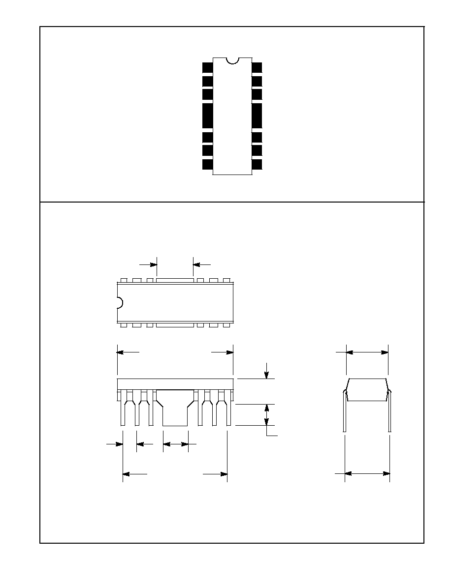
NTE807
Integrated Circuit
TV Sound Channel, 1W
Description:
The NTE807 is a complete 1Watt sound channel in a 16≠Lead DIP type package and is ideally suited
for use in small screen TV or mobile FM radios. This device operates from a single 14V supply and
provides V
CC
/2 output tracking as well as greater than 20dB of ripple rejection. The NTE807 will di-
rectly drive an 8
or 18
speaker and has a true 1W output into the 8
load.
Features:
D
Low Limiting Threshold
D
Low External Parts Count
D
High AM Rejection
D
Single Adjustment Tuning
D
70dB Limiter Gain
D
70dB DC Voltage Control Range
D
Automatic Thermal Shutdown
D
Output Current Limiting
D
10V to 18V Operating Range
D
>
20dB Ripple Rejection
Absolute Maximum Ratings:
Supply Voltage, V
CC
+18V
. . . . . . . . . . . . . . . . . . . . . . . . . . . . . . . . . . . . . . . . . . . . . . . . . . . . . . . . . . . . . . .
Regulator Output Current, I
REG
10mA
. . . . . . . . . . . . . . . . . . . . . . . . . . . . . . . . . . . . . . . . . . . . . . . . . . . .
Input Voltage (Pin10), V
IN
+4.0V
. . . . . . . . . . . . . . . . . . . . . . . . . . . . . . . . . . . . . . . . . . . . . . . . . . . . . . . . .
Operating Temperature Range, T
A
≠40
∞
to +85
∞
C
. . . . . . . . . . . . . . . . . . . . . . . . . . . . . . . . . . . . . . . . . . .
Storage Temperature Range, T
S
≠65
∞
to +150
∞
C
. . . . . . . . . . . . . . . . . . . . . . . . . . . . . . . . . . . . . . . . . . .
Static Electrical Characteristics: (T
A
= +25
∞
C, V
CC
= 14V unless otherwise specified)
Parameter
Symbol Test Pin
Test Conditions
Min
Typ
Max
Unit
Quiescent Supply Current
I
CC
8
V
in
= 0
20
35
55
mA
Terminal Voltage
V
2
2
≠
5.0
≠
V
V
3
3
≠
2.5
≠
V
V
OUT
7
≠
7.0
≠
V
V
REG
9
7.0
8.0
9.0
V
V
IN
10,11
≠
1.4
≠
V
V
14,15
14,15
≠
4.1
≠
V
V
16
16
≠
4.5
≠
V
Dynamic Electrical Characteristics: (@ T
A
= 25
∞
C, V
CC
= 14V, f
o
= 4.5MHz, f
m
= 400Hz,
f = 25kHz, V
in
= 10mV, unless otherwise indicated)
Parameter
Symbol
Test Pin
Test Conditions
Min
Typ
Max
Unit
Input Limiting Threshold
V
TH
7
Note 1
≠
150
≠
µ
V
AM Rejection
AMR
7
Note 2, m = 0.3
30
>
50
≠
dB
Recovered Audio
V
OUT
16
250
400
550
mV
Output Distortion
THD
D
16
≠
<
1.0
3.0
%
Playthrough
7
V
1
= 0V
≠
5.0
25
mV
Power Amp Voltage Gain
A
e
3≠7
V
out
= 1.0V
25
27
29
dB
Output Distortion
THD
D
7
P
OUT
= 1.0W
≠
2.0
10
%
Output Current Limiting
I
OUT
7
R
L
= 0
≠
800
≠
mA
Output Tracking
V
OUT
/V
CC
7/8
V
CC
= 10V to 18V
≠
0.5
≠
V/V
Output Noise
e
n
7
V
in
= 0V, V
1
= 10V
≠
5.0
25
mV
Power Amp Input Impedance
Z
in
3
f = 1.0kHz
≠
50
≠
k
Note 1.,Adjust V
1
for V
out
= 1.4V, then reduce V
in
until V
out
= 1.0V (≠3dB)
Note 2. Adjust V
1
for V
out
= 1.4V