NTE2332
Darlington Silicon NPN Transistor
w
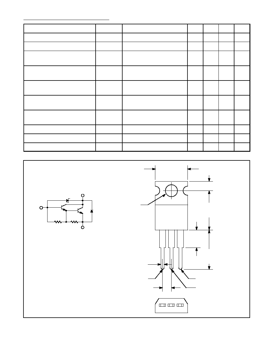
/ Internal Damper & Zener Diode
Description:
The NTE2332 Darlington transistor is especially well suited for use in switching of L load motor driv-
ers, printer hammer drivers, relay drivers, etc.
Features:
D
High DC Current Gain
D
Large Current Capacity and Wide ASO
D
Contains 60
±
10V Avalanche Diode Between Collector and Base
D
Uniformity in Collector≠to≠Base Breakdown Voltage Due to Adoption of Accurate Impurity
Diffusion Process
D
25mJ Reverse Energy Rating
Absolute Maximum Ratings: (T
A
= +25
∞
C, unless otherwise specified)
Collector to Base Voltage, V
CBO
,
60
±
10V
. . . . . . . . . . . . . . . . . . . . . . . . . . . . . . . . . . . . . . . . . . . . . . . . .
Collector to Emitter Voltage, V
CEO
,
60
±
10V
. . . . . . . . . . . . . . . . . . . . . . . . . . . . . . . . . . . . . . . . . . . . . . .
Emitter to Base Voltage, V
EBO
6V
. . . . . . . . . . . . . . . . . . . . . . . . . . . . . . . . . . . . . . . . . . . . . . . . . . . . . . . .
Collector Current, I
C
2A
. . . . . . . . . . . . . . . . . . . . . . . . . . . . . . . . . . . . . . . . . . . . . . . . . . . . . . . . . . . . . . . . .
Peak Collector Current, i
cp
4A
. . . . . . . . . . . . . . . . . . . . . . . . . . . . . . . . . . . . . . . . . . . . . . . . . . . . . . . . . . . .
Base Current, I
B
0.4A
. . . . . . . . . . . . . . . . . . . . . . . . . . . . . . . . . . . . . . . . . . . . . . . . . . . . . . . . . . . . . . . . . .
Collector Dissipation (T
C
= +25
∞
C), P
C
20W
. . . . . . . . . . . . . . . . . . . . . . . . . . . . . . . . . . . . . . . . . . . . . . .
Junction Temperature, T
J
+150
∞
C
. . . . . . . . . . . . . . . . . . . . . . . . . . . . . . . . . . . . . . . . . . . . . . . . . . . . . . . . .
Storage Temperature Range, T
stg
≠55
∞
to +150
∞
C
. . . . . . . . . . . . . . . . . . . . . . . . . . . . . . . . . . . . . . . . . .
Electrical Characteristics: (T
A
= +25
∞
C, unless otherwise specified)
Parameter
Symbol
Test Conditions
Min
Typ
Max
Unit
Collector Cutoff Current
I
CEO
V
CB
= 40V, I
E
= 0
≠
≠
10
µ
A
Emitter Cutoff Current
I
EBO
V
EB
= 5V, I
C
= 0
≠
≠
2
mA