NTE914
Integrated Circuit
Zero¡Voltage Switch
Description:
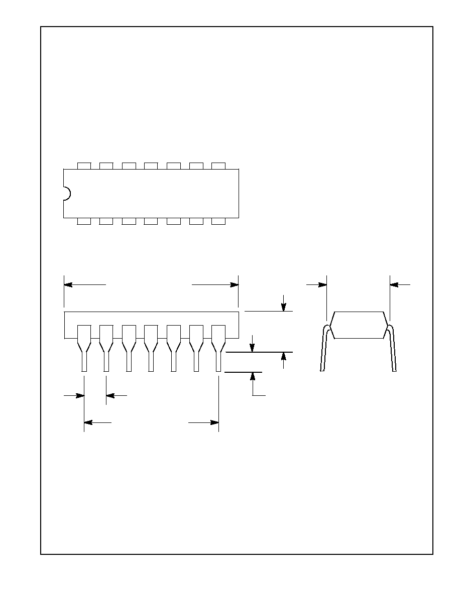
The NTE914 zero¡voltage switch is a monolithic silicon integrated circuit in a 14¡Lead DIP type pack-
age designed to control a thyristor in a variety of AC power switching applications for AC input voltages
of 24V, 120V, 208/230V, and 277V at 50/60Hz and 400Hz. The NTE914 incorporates 4 functional
blocks as follows:
Limiter¡Power Supply: Permits operation directly from an AC line.
Differential ON/OFF Sensing Amplifier: Tests the condition of external sensors or command
signals. Hysteresis or proportional¡control capability may easily be implemented in this section.
Zero¡Crossing Detector: Synchronizes the output pulses of the circuit at the time when the
AC cycle is at zero voltage point; thereby eliminating radio¡frequency interference (RFI) when
used with resistive loads.
TRIAC Gating Circuit: Provides high current pulses to the gate of the power controlling thyristor.
The NTE914 also provides the following important auxiliary functions:
A built¡in protection circuit that may be actuated to remove drive from the TRIAC if the sensor
opens or shorts.
Thyristor firing may be inhibited through the acting of an internal diode gate connected to Pin1.
High¡power DC comparator operation is provided by overriding the action of the zero¡crossing
detector. This is accomplished by connecting Pin12 to Pin7. Gate current to the thyristor is
continuous when Pin13 is positive with respect to Pin9.
Features:
D
24V, 120V, 208/230V, 277V at 50Hz, 60Hz, or 400Hz Operation
D
Differential Input
D
Low Balance Input Current: 1
╡
A Max
D
Built¡In Protection Circuit or Opened or Shorted Sensor
D
Sensor Range: R
X
= 2 to 100k
D
DC Mode
D
External Trigger
D
External Inhibit
D
DC Supply Voltage: 14V Max
Applications:
D
Relay Control
D
Valve Control
D
Synchronous Switching of Flashing Lights
D
ON/OFF Motor Switching
D
Differential Comparator with Self¡Contained Power Supply for Industrial Applications
D
Photosensitive Control
D
Power One¡Shot Control
D
heater Control
D
Lamp Control
Absolute Maximum Ratings: (T
A
= +25
░
C unless otherwise specified)
DC Supply Voltage (Between Pin2 and Pin7)
14V
. . . . . . . . . . . . . . . . . . . . . . . . . . . . . . . . . . . . . . . . . . .
DC Supply Voltage (Between Pin2 and Pin8)
10V
. . . . . . . . . . . . . . . . . . . . . . . . . . . . . . . . . . . . . . . . . . .
Peak Supply Current (Between Pin5 and Pin7)
▒
50mA
. . . . . . . . . . . . . . . . . . . . . . . . . . . . . . . . . . . . . .
Output Pulse Current (Pin4)
150mA
. . . . . . . . . . . . . . . . . . . . . . . . . . . . . . . . . . . . . . . . . . . . . . . . . . . . . .
Power Dissipation (T
A
+55
░
C), P
D
700mW
. . . . . . . . . . . . . . . . . . . . . . . . . . . . . . . . . . . . . . . . . . . . . .
Derate Linearly Above 55
░
C
6.67mW/
░
C
. . . . . . . . . . . . . . . . . . . . . . . . . . . . . . . . . . . . . . . . . . . .
Operating Ambient Temperature Range, T
opr
¡55
░
to +125
░
C
. . . . . . . . . . . . . . . . . . . . . . . . . . . . . . . . .
Storage Temperature Range, T
stg
¡65
░
to + 150
░
C
. . . . . . . . . . . . . . . . . . . . . . . . . . . . . . . . . . . . . . . . .
Lead Temperature (During Soldering 1/16" from case, 10sec max), T
L
+265
░
C
. . . . . . . . . . . . . . . . .
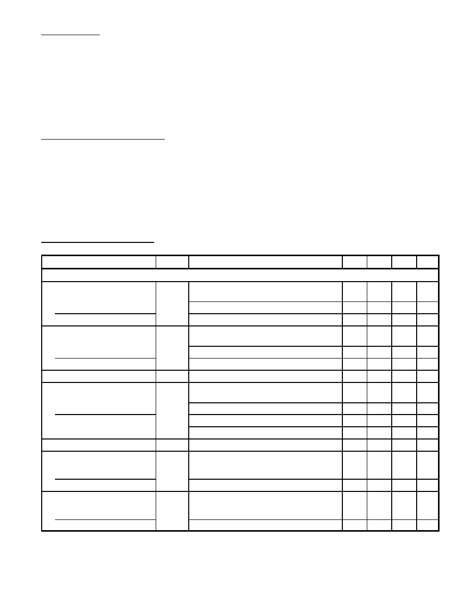
Electrical Characteristics: (T
A
= +25
░
C, All voltages are measured with respect to Pin7 unless
otherwise specified)
Parameter
Symbol
Test Conditions
Min
Typ
Max
Unit
For Operation at 120V
rms
, 50¡60Hz (AC Line Voltage) (Note 1)
DC Supply Voltage (Inhibit Mode)
At 50/60Hz
V
S
R
S
= 8k
, I
L
= 0
6.1
6.5
7.0
V
R
S
= 5k
, I
L
= 2mA
¡
6.4
¡
V
At 400Hz
R
S
= 10k
, I
L
= 0
¡
6.8
¡
V
DC Supply Voltage (Pulse Mode)
At 50/60Hz
V
S
R
S
= 8k
, I
L
= 0
6.0
6.4
7.0
V
R
S
= 5k
, I
L
= 2mA
¡
6.3
¡
V
At 400Hz
R
S
= 10k
, I
L
= 0
¡
6.7
¡
V
Gate Trigger Current
I
GT
(4)
V
GT
= 1V, Pin3 and Pin4 Connected
¡
105
¡
mA
Peak Output Current (Pulsed)
With Internal Power Supply
I
OM
(4)
V
GT
= 0, Pin3 Open
50
84
¡
mA
V
GT
= 0, Pin3 and Pin2 Connected
90
124
¡
mA
With External Power Supply
V+ = 12V, V
GT
= 0, Pin3 Open
¡
170
¡
mA
V+ = 12V, V
GT
= 0, Pin3 and Pin2 Connected
¡
240
¡
mA
Inhibit Input Ratio
V
9
/V
2
Voltage Ratio of Pin9 to Pin2
0.465 0.485 0.520
Total Gate Pulse Duration
(Positive dv/dt)
50¡60Hz
t
P
C
EXT
= 0
70
100
140
╡
s
400Hz
C
EXT
= 0, R
EXT
=
¡
12
¡
╡
s
Total Gate Pulse Duration
(Negative dv/dt)
50¡60Hz
t
N
C
EXT
= 0
70
100
140
╡
s
400Hz
C
EXT
= 0, R
EXT
=
¡
10
¡
╡
s
Note 1. The values given in the "Electrical Characteristics" chart at 120V also apply for operation at
input voltages of 24V, 208/230V, and 277V, except for Pulse Duration. However, the series
resistor (R
S
) must have the indicated value shown in Table 1 for the specified value.

Electrical Characteristics (Cont'd): (T
A
= +25
░
C, All voltages are measured with respect to Pin7
unless otherwise specified)
Parameter
Symbol
Test Conditions
Min
Typ
Max
Unit
For Operation at 120V
rms
, 50¡60Hz (AC Line Voltage) (Note 1)
Pulse Duration After Zero
Crossing (50¡60Hz)
For Positive dv/dt
t
P1
C
EXT
= 0, R
EXT
=
¡
50
¡
╡
s
For Negative dv/dt
t
N1
¡
60
¡
╡
s
Output Leakage Current
(Inhibit Mode)
I
4
¡
0.001
10
╡
s
Input Bias Current
I
I
¡
220
1000
nA
Common¡Mode Input Voltage
Range
V
CMR
Pin9 and Pin13 Connected
1.5 to 5.0
V
Sensitivity (Pulse Mode)
V
13
Pin12 Open, Note 2
¡
6
¡
mV
Note 1. The values given in the "Electrical Characteristics" chart at 120V also apply for operation at
input voltages of 24V, 208/230V, and 277V, except for Pulse Duration. However, the series
resistor (R
S
) must have the indicated value shown in Table 1 for the specified value.
Note 2. Required voltge change at Pin13 to either turn OFF the TRIAC or turn ON the TRIAC when
OFF.
Table 1:
AC Input Voltage (50/60 or 400Hz)
Input Series Resistor, R
S
Dissipation Rating for R
S
V AC
k
W
W
24
2
0.5
120
10
2.0
208/230
20
4.0
277
25
5.0
Sensor Network
Failsafe Input
Off¡On Sense Amp
1
2
3
4
Inhibit Input
Sensor Network
Current Boost
Thyristor Gate
5
AC Input
6
External Trigger
7
Common
14
13
12
11
Zero¡Crossing Det Input
Off¡On Sense Amp
10
Off¡On Sense Amp
9
8
Common
Pin Connection Diagram