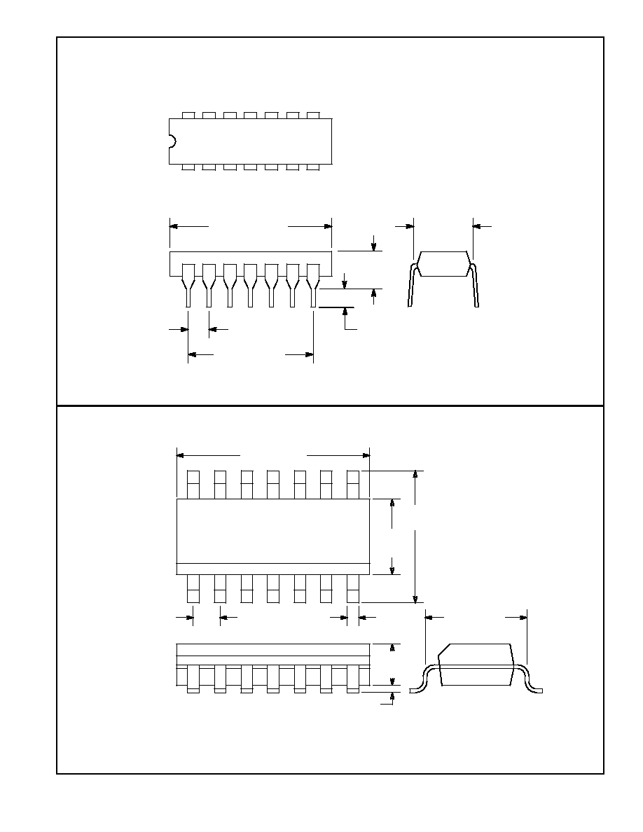
NTE927D & NTE927SM
Integrated Circuit
Differential Video Amplifier
Description:
The NTE927D and NTE927SM are two≠stage, differential input, differential output, wide≠band video
amplifiers. The use of internal series≠shunt feedback gives wide band bandwidth with low phase dis-
tortion and high gain stability. Emitter≠follower outputs provide a high current drive, low impedance
capability. Its 120MHz bandwidth and selectable gains of 10, 100, and 400, without need for frequen-
cy compensation, make it a very useful circuit for memory element drivers, pulse amplifiers, and wide
band gain stages.
Features:
D
120MHz Bandwidth
D
250k
Input Resistance
D
No Frequency Compensation Required
D
Selectable Gains of 10, 100 and 400
D
High Common Mode Rejection Ratio at High Frequencies
Applications:
D
Magnetic Tape Systems
D
Disk File Memories
D
Thin and Thick Film Memories
D
Woven and Plated Wire Memories
D
Wide Band Video Amplifiers
Absolute Maximum Ratings:
Differential Input Voltage
±
5V
. . . . . . . . . . . . . . . . . . . . . . . . . . . . . . . . . . . . . . . . . . . . . . . . . . . . . . . . . . . .
Common Mode Input Voltage
±
6V
. . . . . . . . . . . . . . . . . . . . . . . . . . . . . . . . . . . . . . . . . . . . . . . . . . . . . . . .
Supply Voltage, V
CC
±
8V
. . . . . . . . . . . . . . . . . . . . . . . . . . . . . . . . . . . . . . . . . . . . . . . . . . . . . . . . . . . . . . . .
Output Current, I
O
10mA
. . . . . . . . . . . . . . . . . . . . . . . . . . . . . . . . . . . . . . . . . . . . . . . . . . . . . . . . . . . . . . . .
Power Dissipation (Note 1), P
D
500mW
. . . . . . . . . . . . . . . . . . . . . . . . . . . . . . . . . . . . . . . . . . . . . . . . . . .
Junction Temperature, T
J
+100
∞
C
. . . . . . . . . . . . . . . . . . . . . . . . . . . . . . . . . . . . . . . . . . . . . . . . . . . . . . . . .
Storage Temperature Range, T
stg
≠65
∞
to +150
∞
C
. . . . . . . . . . . . . . . . . . . . . . . . . . . . . . . . . . . . . . . . . .
Operating Temperature Range, T
opr
0
∞
to +70
∞
C
. . . . . . . . . . . . . . . . . . . . . . . . . . . . . . . . . . . . . . . . . . .
Lead Temperature (Soldering, 10sec), T
L
+260
∞
C
. . . . . . . . . . . . . . . . . . . . . . . . . . . . . . . . . . . . . . . . . . .
Note 1. For operation at elevated temperatures, derate device based on a thermal resistance of
+150
∞
C/W junction to ambient or +45
∞
C/W junction to case.
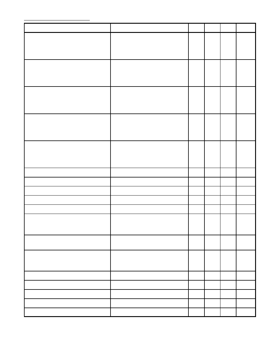
Electrical Characteristics: (T
A
= +25
∞
C, unless otherwise specified, V
S
=
±
6V)
Parameter
Test Conditions
Min
Typ
Max
Unit
Differential Voltage Gain
Gain 1 (Note 2)
Gain 2 (Note 3)
Gain 3 (Note 4)
R
L
= 2k
, V
OUT
= 3V
p≠p
250
80
8.0
400
100
10
600
120
12
Bandwidth
Gain 1
Gain 2
Gain 3
≠
≠
≠
40
90
120
≠
≠
≠
MHz
Rise Time
Gain 1
Gain 2
Gain 3
≠
≠
≠
10.5
4.5
2.5
≠
≠
≠
ns
Propagation Delay
Gain 1
Gain 2
Gain 3
V
OUT
= 1V
p≠p
≠
≠
≠
7.5
6.0
3.6
≠
10
≠
ns
Input Resistance
Gain 1
Gain 2
Gain 3
≠
10
≠
4.0
30
250
≠
≠
≠
k
Input Capacitance
Gain 2
≠
2.0
≠
pF
Input Offset Current
≠
0.4
5.0
µ
A
Input Bias Current
≠
9.0
30
µ
A
Input Noise Voltage
BW = 1kHz to 10MHz
≠
12
≠
µ
Vrms
Input Voltage Range
±
1.0
≠
≠
V
Common Mode Rejection Ratio
Gain 2
Gain 2
V
CM
=
±
1V, f
100kHz
V
CM
=
±
1V, f = 5MHz
60
≠
86
60
≠
≠
dB
Supply Voltage Rejection Ratio
Gain 2
V
S
=
±
0.5V
50
70
≠
dB
Output Offset Voltage
Gain 1
Gain 2 and 3
R
L
=
≠
≠
0.6
0.35
1.5
1.5
V
Output Common Mode Voltage
R
L
=
2.4
2.9
3.4
V
Output Voltage Swing
R
L
= 2k
3.0
4.0
≠
Output Sink Current
2.5
3.6
≠
mA
Output Resistance
≠
20
≠
Power Supply Current
R
L
=
≠
18
24
mA