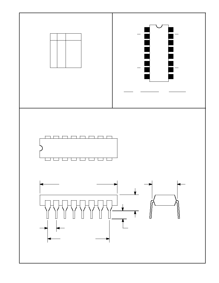
NTE9370
Integrated Circuit
HTL, Quad DÙType FlipÙFlop
Description:
Four DÙtype flipÙflops utilizing a common clock line make up the NTE9370. Each flipÙflop has compli-
mentary passive pull up outputs with a single D input. This circuit is ideal as a quad latch for temporary
storage of 4Ùbit binary numbers.
Data is transferred from D inputs to outputs when the clock line is low. With the clock line high, output
data is held and D inputs are ignored.
Absolute Maximum Ratings:
Supply Voltage:
Continuous
16.5V
. . . . . . . . . . . . . . . . . . . . . . . . . . . . . . . . . . . . . . . . . . . . . . . . . . . . . . . . . . . . . . . .
Pulsed
(<
0.1sec)
18V
. . . . . . . . . . . . . . . . . . . . . . . . . . . . . . . . . . . . . . . . . . . . . . . . . . . . . . . . . . . .
Input Voltage
Ù0.5V to 16.5V
. . . . . . . . . . . . . . . . . . . . . . . . . . . . . . . . . . . . . . . . . . . . . . . . . . . . . . . . . . . .
Voltage Applied to Output
Ù0.5V to +16.5V
. . . . . . . . . . . . . . . . . . . . . . . . . . . . . . . . . . . . . . . . . . . . . . . .
Continuous Sink Current (T
A
= +25
¯
C):
Continuous
15mA
. . . . . . . . . . . . . . . . . . . . . . . . . . . . . . . . . . . . . . . . . . . . . . . . . . . . . . . . . . . . . . . .
Surge (
<
1sec)
20mA
. . . . . . . . . . . . . . . . . . . . . . . . . . . . . . . . . . . . . . . . . . . . . . . . . . . . . . . . . . . .
Output Short Circuit Duration to GND
Continuous
. . . . . . . . . . . . . . . . . . . . . . . . . . . . . . . . . . . . . . . . . .
Operating Temperature Range, T
opr
Ù30
¯
to +85
¯
C
. . . . . . . . . . . . . . . . . . . . . . . . . . . . . . . . . . . . . . . . .
Storage Temperature Range, T
stg
Ù55
¯
to +100
¯
C
. . . . . . . . . . . . . . . . . . . . . . . . . . . . . . . . . . . . . . . . . .
Lead Temperature (During Soldering, 1/16" from case, 10sec max), T
L
+300
¯
C
. . . . . . . . . . . . . . . . .
Electrical Characteristics: (V
CC
= 12V
Ý
1V unless otherwise specified)
Parameter
Symbol
Test Conditions
Min
Typ
Max Unit
Input Threshold Voltage, Low
V
IL
Guaranteed input low threshold for all inputs
5
Ù
Ù
V
Input Threshold Voltage, High
V
IH
Guaranteed input high threshold for all inputs
Ù
Ù
6.5
V
Input Current, Low (1 Unit Load)
I
IL
V
CC =
Max, V
IN
= V
OL1
max
Ù
Ù
2.1
mA
Input Leakage Current (1 Unit Load)
I
IH
V
CC =
Max, V
IN
= V
CC
Ù
Ù
10
ç
A
Output Low Voltage
V
OL
V
CC
= Min, V
IL
= 5V V
IH
= 6.5V,
Ù
Ù
1.5
V
Output High Voltage
V
OH
I
OL
= F.O. x U.L.
10
Ù
Ù
V
Test Supply Voltage
V
CC
11
12
13
V
Note 1. F.O. is fanout in unit loads (U.L.). A unit load is defined by the above input specifications.