NVE Corporation 11409 Valley View Road, Eden Prairie, Minnesota 55344 USA
(800) 467-7141 Web:
www.nve.com
Email:
info@nve.com
04/28/03
GT Sensors
Precision Gear Tooth and Encoder Sensors
NVE's GT Sensor
products are based on a Low Hysteresis GMR sensor material, and
are designed for use in industrial speed applications where magnetic detection of gear
teeth and magnetic encoder wheels is required.
GT Sensors with both analog and digital outputs are available. The analog parts feature
the large signal and robust characteristics which NVE's GMR materials are known for
(NVE's GMR sensors are not damaged by extremely large magnetic fields). The sensor
elements themselves are designed to provide usable output with even the smallest gear
teeth. Single and double output versions are available; the second output is phase shifted
with respect to the first, to provide quadrature for determining direction.
The digital sensors take advantage of the high performance characteristics of GMR
sensors to provide a 50% duty cycle output with a wide tolerance in airgap and
temperature variations.
GT Sensors are available in low
profile MSOP8, TDFN SO8, and
TDFN6 packages, in order to fit into
the tightest possible spaces. An
evaluation kit is available,
containing a selection of sensors,
magnets, and PCBs, so that the user
can test the parts in their application.

ABL Sensors
NVE Corporation 11409 Valley View Road, Eden Prairie, Minnesota 55344 USA
(800) 467-7141 Web:
www.nve.com
Email:
info@nve.com
04/28/03
ABL Sensors
Single/Double Bridge Gear Tooth And Encoder Sensors
Features:
Large Airgap
Direct Analog Output
DC (Zero Speed) Operation
Sine / Cosine Outputs
Precise Spacing and Phase Shifting Between Sensor Elements
Excellent Temperature and Voltage Performance
Small, Low Profile Surface Mount Packages
Applications:
Linear and Angular Speed Sensing
Linear and Angular Position Sensing
Direction Detection
Description:
The ABL Series GT Sensors are differential sensor elements that provide an analog
sinusoidal output signal when used with a bias magnet and gear tooth or a magnetic
encoder. These chips use NVE's proprietary GMR sensor elements, featuring an
extremely large output signal from the raw sensor element, which is stable over the rated
temperature and voltage range. As a result, ABL Series GT Sensors feature excellent
airgap performance and an extremely stable operating envelope, as well as the robust
reliability characteristics that NVE sensors are known for.
Three different standard spacings are available, for use with fine and coarse pitch
encoders and gear teeth. Both single bridge and double bridge configurations are also
available; double bridges are used to generate sine/cosine outputs. In addition to the
standard spacings, NVE can provide custom spacings and multiple sensor elements
tailored to the individual customer's application for a nominal design and tooling charge.
Contact NVE for further details.
For digital output applications, these sensors can be used with NVE's DD001-12 signal
processing IC, which converts their output into a 50% duty cycle modulated current
signal. This IC allows placement of the ABL sensor in a very small housing, with wires
running from the sensor to the signal processing IC in a remote location. In this fashion
ABL series sensors can be used in M8 and smaller housings.
ABL Sensors
NVE Corporation 11409 Valley View Road, Eden Prairie, Minnesota 55344 USA
(800) 467-7141 Web:
www.nve.com
Email:
info@nve.com
04/28/03
Specifications:
Property
Min
Typ
Max
Unit
Single Bridge Resistance
4K
5K
7K
Ohms
Input Voltage
<1
1
30
1
Volts
Operating Temperature Range
-50
+170
�C
Offset Voltage
-4
+4
mV/V
Linear Range
+/-5
+/-100
Oe
Linearity of Output
98
%
2
Hysteresis
2
%
2
Saturation of GMR Sensor Elements
-180
+180
Oe
3
Single Resistor Sensitivity
.04
%
R/Oe
4
Max Output
80
mV/V
Temperature Coefficient of Resistance
+0.3
%/
�C
ESD
400
V
5
Notes:
1.
ABL Series sensors have a purely ratiometric output. They will operate with input voltages of
0.1V or lower. The output signal will scale proportionally with the input voltage. Maximum
voltage will be limited by the power dissipation allowable in the package and user installation.
See the package section for more details.
2.
Linearity and Hysteresis measured across linear operating range, unipolar operation.
3.
Application of a magnetic field in excess of this value will saturate the GMR sensor elements,
and no further output will be obtained. No damage occurs to the sensor elements when
saturated; NVE GMR sensors will not be damaged by any large magnetic field.
4.
Percent change in resistance with application of 1 Oersted of magnetic field; corresponds to an
8% change in resistance with 200 Oersteds of applied magnetic field (1 Oersted = 1 Gauss in
air, or 0.1 milli-Tesla).
5.
Pin to pin voltage, Human Body Model for ESD
ABL Sensors
NVE Corporation 11409 Valley View Road, Eden Prairie, Minnesota 55344 USA
(800) 467-7141 Web:
www.nve.com
Email:
info@nve.com
04/28/03
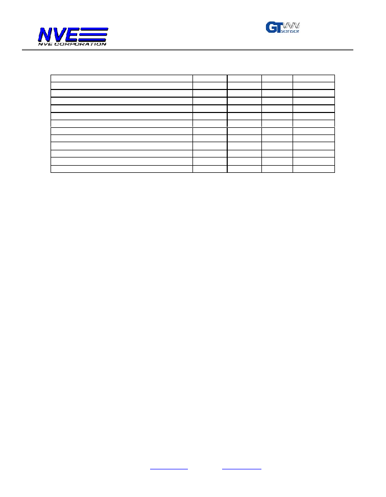
IC Drawings:
Note: ABL006 Sensor Element Size and Spacing Not Shown
Center of Die and Package
Die Outline
ABL004 Sensor Element Size and Spacing
- All dimensions in mm
R1, R2
- Sensor elements are located symmetrically about the center of the IC.
- All resistors are 5K Ohms
R3, R4
Center of Die and Package
Die Outline
ABL005 Sensor Element Size and Spacing
R1, R2
R3, R4
- All dimensions in mm
- Sensor elements are located symmetrically about the center of the IC.
- All resistors are 5K Ohms
ABL Sensors
NVE Corporation 11409 Valley View Road, Eden Prairie, Minnesota 55344 USA
(800) 467-7141 Web:
www.nve.com
Email:
info@nve.com
04/28/03
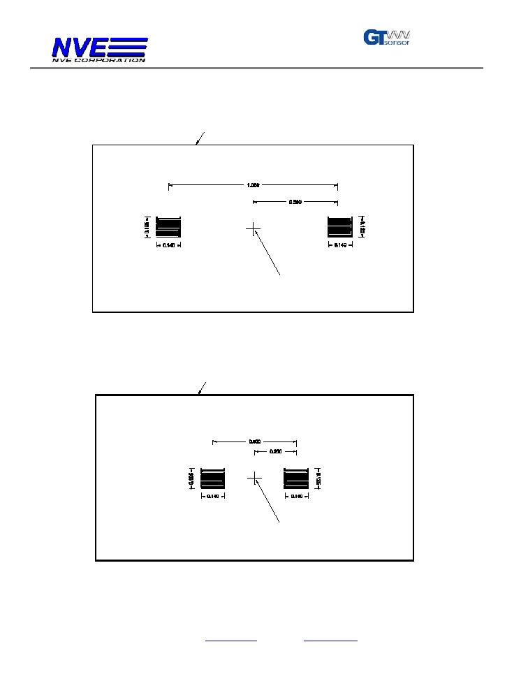
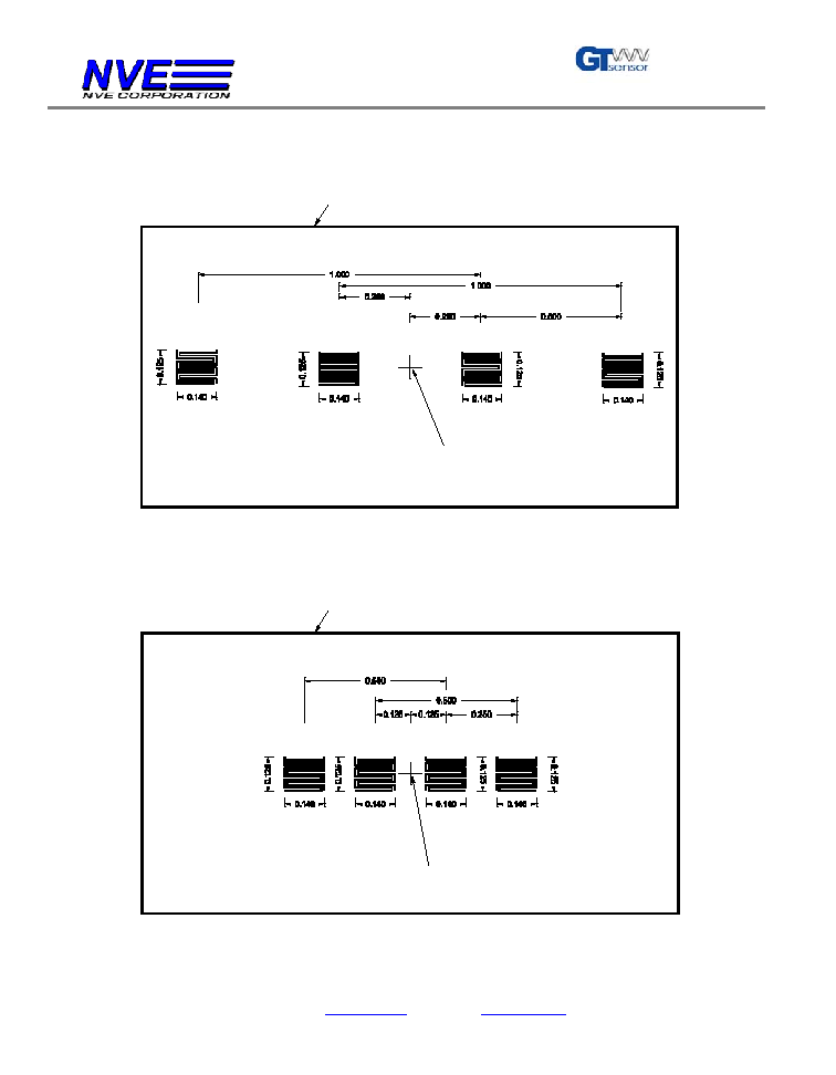
Note: ABL016 Sensor Element Size and Spacing Not Shown
Center of Die and Package
Die Outline
ABL014 Sensor Element Size and Spacing
- All dimensions in mm
- Sensor elements are located symmetrically about the center of the IC.
- All resistors are 5K Ohms
R5, R6
R1, R2
R3, R4
R7, R8
Center of Die and Package
Die Outline
ABL015 Sensor Element Size and Spacing
R1, R2
R3, R4
R5, R6
R7, R8
- All dimensions in mm
- Sensor elements are located symmetrically about the center of the IC.
- All resistors are 5K Ohms