
GMR Switch Precision Digital Sensors
NVE Corporation 11409 Valley View Road, Eden Prairie, Minnesota 55344 USA
(800) 467-7141 Web:
www.nve.com
Email:
info@nve.com
11/15/02
GMR Switch
Precision Digital Sensors
When GMR sensor elements are combined with digital on-board signal processing
electronics, the result is the GMR Switch. The GMR Switch offers unmatched precision
and flexibility in magnetic field sensing.
The GMR Switch will accurately and reliably sense magnetic fields with less error than
any other magnetic sensor on the market today. In addition, there is little shift in the
magnetic field operate point of the GMR Switch over voltage and temperature extremes.
This gives NVE's customer the ability to make a high precision, high tolerance magnetic
sensing assembly.
The GMR switch can operate over a wide range of magnetic fields, and is the most
precise magnetic sensor on the market. It is the clear choice when a digital output signal
is required of a magnetic sensor.
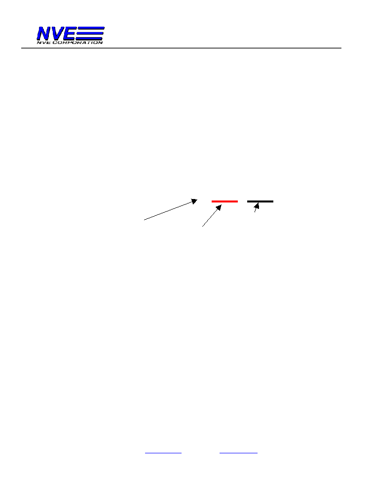
Magnetic
Operate Point
(Gauss)
50
150
Operate Point Error Band for Typical Magnetic Sensors
(4.5V to 30V, -40C to +125C)
Allegro 3141LLT
(Hall Effect)
Honeywell SS441A
(Hall Effect)
Honeywell 2SSP
(AMR)
NVE AD023-00
(GMR)
NVE AD021-00
(GMR)
NVE AD022-00
(GMR)
The GMR Switch Holds Tighter
Operate Point Specifications
Than Any Competing Product!
200

GMR Switch Precision Digital Sensors
NVE Corporation 11409 Valley View Road, Eden Prairie, Minnesota 55344 USA
(800) 467-7141 Web:
www.nve.com
Email:
info@nve.com
11/15/02
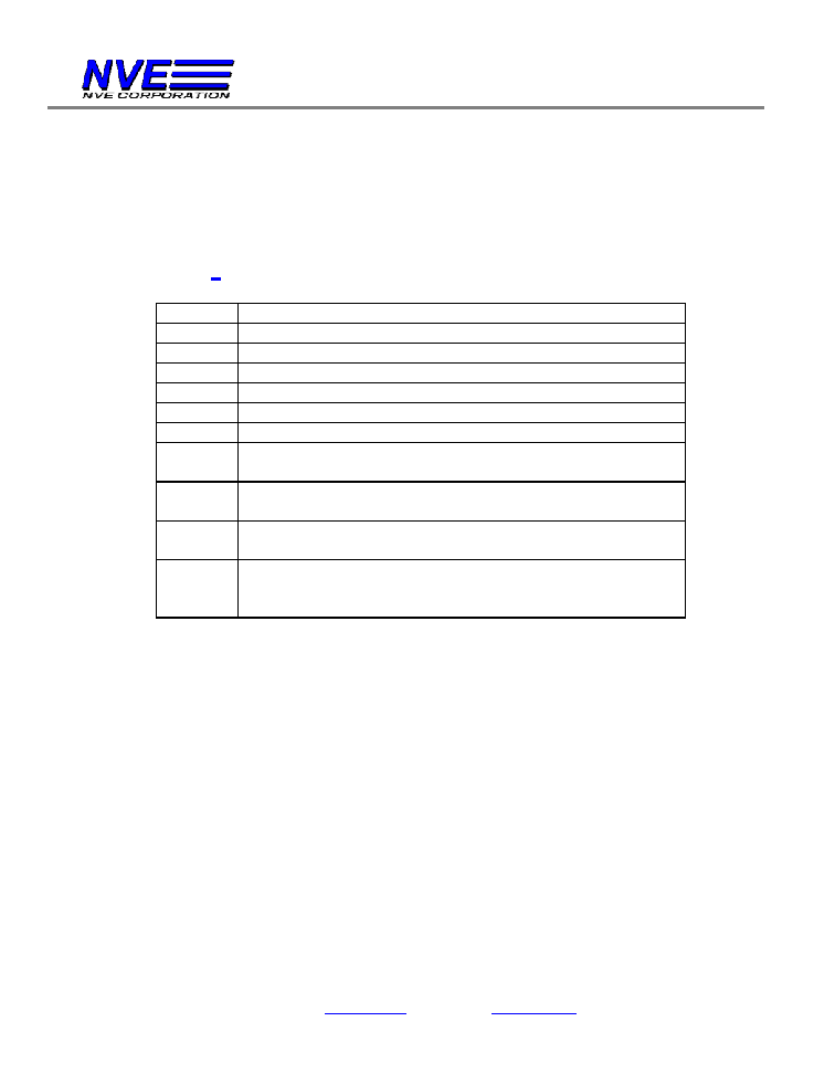
Quick Reference: GMR Switch Digital Sensors
The following table lists some of NVE's most popular GMR Switch products and their
key specifications:
Part Number
Typical
Magnetic
Operate
Point
(Oe
1
)
Typical
Magnetic
Release
Point
(Oe
1
)
Output
Type
2
Maximum
Operation
Temperature
(�C)
Package
Type
3
NVE AD004-02
20
10
Sink
125
SOIC8
NVE AD005-02
40
25
Sink
125
SOIC8
NVE AD021-00
20
10
Sink
125
MSOP8
NVE AD022-00
40
25
Sink
125
MSOP8
NVE AD024-00
28
14
Sink
125
MSOP8
NVE AD124-00
28
14
Source
125
MSOP8
NVE AD621-00
20
10
Sink +
Source
125
MSOP8
NVE AD824-00
28
14
2 Sinks +
SCP
125
MSOP8
NVE ADH025-00
11
5
Sink
150
MSOP8
Notes:
1.
1 Oersted (Oe) = 1 Gauss in air
2.
Output Types:
Sink = Up to 20mA current sink
Source = Up to 20mA current source
SCP = Short Circuit Protection available for external transistor
3.
See Appendix for package dimensions
Note on Availability of Products
NVE keeps about 25 of the most popular types of GMR Switch products in
stock at our manufacturing facility. However, because there are over 100
different varieties of GMR Switch parts, some part numbers may require a 6 to 8
week lead time before production quantities are available. Please contact NVE
for further information.
GMR Switch Product Selection Guide
NVE Corporation 11409 Valley View Road, Eden Prairie, Minnesota 55344 USA
(800) 467-7141 Web:
www.nve.com
Email:
info@nve.com
11/15/02
GMR Switch Product Selection Guide
NVE's GMR Switch is available in a wide range of packaging, output type, and magnetic
trigger field varieties. The purpose of this selection guide is to explain the different
output and packaging options, as well as to provide information on how to specify the
correct part number when ordering.
All NVE GMR Switch product part numbers follow the same general form. As shown
below, the first "x" in the part number specifies output type and available voltage
regulator output, the next two x's specify trigger field and direction of sensitivity, and the
last pair specify the package type. The following sections define these variations in
detail.
NVE AD
x
xx
-xx
Output Type and Available Regulator
The first numeric digit of the part number NVE ADxxx-xx specifies the output type, and
the availability of a regulated voltage supply on a separate pin. The following four output
types are available:
20 mA Current Sink
20 mA Current Source
Separate 20 mA Sink and Source
Two Separate 20 mA Sinks
All outputs turn ON when the magnetic field is applied. An output that turns OFF when
the magnetic field is applied is available as a custom product; please consult NVE.
Some of NVE's GMR Switches also feature a regulated supply voltage available external
to the part on a separate pin. This regulator provides a 5.8V reference capable of
supplying up to 3 mA of drive current. This regulated output may be used to run an LED
or other low power device.
Output Type and
Available Regulator
Package Type
Trigger Field, Direction of
Sensitivity, Low Voltage Operation
GMR Switch Product Selection Guide
NVE Corporation 11409 Valley View Road, Eden Prairie, Minnesota 55344 USA
(800) 467-7141 Web:
www.nve.com
Email:
info@nve.com
11/15/02
In addition to these options, NVE recently introduced a GMR Switch that has provisions
for shutting down an external power transistor in case a short circuit is detected. This is
useful in applications where the finished sensor assembly must be "bulletproof," or
immune to improper connection.
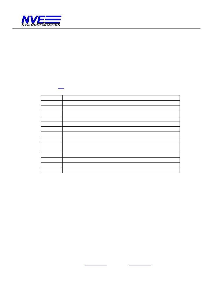
The following table defines the first digit in the NVE AD part number:
NVE AD
x
xx-xx
Number
Meaning
0
20mA Current Sink
1
20 mA Current Source
2
Separate 20mA Current Sink and 20mA Current Source
3
Two Separate 20mA Current Sinks
4
20mA Current Sink + Regulated Output Voltage
5
20 mA Current Source + Regulated Output Voltage
6
Separate 20mA Current Sink and 20mA Current Source +
Regulated Output Voltage
7
Two Separate 20mA Current Sinks + Regulated Output
Voltage
8
Two Separate 20mA Current Sinks + Regulated Output
Voltage + Short Circuit Detection and Shut-Off
9
Separate 20mA Current Sink and 20mA Current Source +
Regulated Output Voltage + Short Circuit Detection and
Shut-Off
Trigger Field, Direction of Sensitivity, Low Voltage Operation
The second and third numeric digits of the part number NVE ADxxx-xx specify the
magnetic trigger field and direction of sensitivity of the part. Five different magnetic
trigger fields are available for the GMR Switch:
-
10 Gauss (10 Oe, 1.0 mT, 0.8 kA/m)
-
20 Gauss (20 Oe, 2.0 mT, 1.6 kA/m)
-
28 Gauss (28 Oe, 2.8 mT, 2.23 kA/m)
-
40 Gauss (40 Oe, 4.0 mT, 3.2 kA/m)
-
80 Gauss (80 Oe, 8.0 mT, 6.4 kA/m)
Other magnetic trigger field levels ranging up to 250 Gauss are available on a custom
basis; please contact NVE.
GMR Switch Product Selection Guide
NVE Corporation 11409 Valley View Road, Eden Prairie, Minnesota 55344 USA
(800) 467-7141 Web:
www.nve.com
Email:
info@nve.com
11/15/02
In addition to defining the magnetic operate point, these two digits are used to define the
direction of sensitivity and optional low voltage operation. The GMR Switch can be
ordered in Standard Axis or Cross Axis directions of sensitivity; for definitions please see
NVE AD Series Sensitivity Direction and Pin Configuration later in this section.
NVE also makes a GMR Switch with the on-chip voltage regulator bypassed. This limits
the voltage range of the part, but allows it to operate at voltages as low as 3.0V.
The following table defines the second and third digits in the NVE AD part number:
NVE AD x
xx
-xx
Number
Meaning
04
20 Gauss OP, Standard Direction of Sensitivity
05
40 Gauss OP, Standard Direction of Sensitivity
06
80 Gauss OP, Standard Direction of Sensitivity
20
28 Gauss OP, Standard Direction of Sensitivity
21
20 Gauss OP, Cross Axis Direction of Sensitivity
22
40 Gauss OP, Cross Axis Direction of Sensitivity
23
80 Gauss OP, Cross Axis Direction of Sensitivity
24
28 Gauss OP, Cross Axis Direction of Sensitivity
25
10 Gauss OP, Cross Axis Direction of Sensitivity
(ADH Series Only; see page 38)
81
20 Gauss OP, Cross Axis Direction of Sensitivity, Low Volt
82
40 Gauss OP, Cross Axis Direction of Sensitivity, Low Volt
83
80 Gauss OP, Cross Axis Direction of Sensitivity, Low Volt
84
28 Gauss OP, Cross Axis Direction of Sensitivity, Low Volt
Note: For parts that operate at 10 Gauss, see the following section describing the NVE
ADH Series sensors.
NVE AD Series Sensitivity Direction and Pin Configuration
Pin configuration is for the NVE AD Series GMR Switches is given in the following
diagrams. In addition, most GMR Switch parts are available with a choice of two
directions of sensitivity. "Standard" direction of sensitivity is defined as the direction
parallel to the edge of the package containing the pins. "Cross-Axis" direction of