 | –≠–ª–µ–∫—Ç—Ä–æ–Ω–Ω—ã–π –∫–æ–º–ø–æ–Ω–µ–Ω—Ç: MSM9800 | –°–∫–∞—á–∞—Ç—å:  PDF PDF  ZIP ZIP |

FEBL9800-03
1Semiconductor
This version: Jan. 2002
Previous version: Mar. 2000
MSM9800/9836 EVA Board
Voice ROM Evaluation Board for MSM9802/9803/9805/9836
1/15
GENERAL DESCRIPTION
The MSM9800/36 Evaluation Board is designed to evaluate sound data, created by using OKI's Sound Analysis
and Editing tool
(
AR762/203/204
)
, for use with MSM9802/MSM9803/MSM9805/MSM9836.
FEATURES
∑
512 Kbit/1 Mbit/2 Mbit/4 Mbit EPROM can be used for evaluation.
∑
Power Supply:
4.75 to 5.25V
∑
Clock Oscillation:
4.096 MHz Ceramic Oscillation
The board is not functional with CR oscillation. Input to the XT/
CR pin is
disabled.
NOTE
Some operations may not be identical to those with an actual target device. Further description is given later in
this document after Page 9.
FEBL9800-03
1Semiconductor
MSM9800/9836 EVA Board
2/15
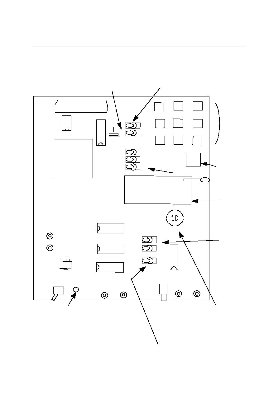
BOARD LAYOUT
Board Layout
(
Top View
)
CPU/STD Selector Switch
Phrase
Selector/Trigger
Key Pad for
Stand-alone
operation
Address Selector
Switch for Stand-
alone operation
EPROM Socket
Output Pins for
Dynamic Speaker
Mini-jack for
Dynamic Speaker
EPROM Size
Selector Switches
Sound Level
Control
For External Control
LED Indicator
Amplifier Selector Switch
Target Device
Selector Switches
MSM9836
ACT16244
EXT/INT Selector Switch
MSM9805
POWER
REG
V
DD
LED
GND
AOUT
VREF
INT
A
M
P
9805
9836
EXT
A
M
P
M
S
C1157RS
100K VR
1
2
3
4
5
6
7
0
R
S
T
2M
1
M
512K
4M
(ALL O
FF)
INT
S
T
D
EXT
CPU
A3
~
A
0
HEX
SW
SP J
a
c
k
SP +
SP ≠
EPROM
32-PIN TEXTOOL
ALT
E
RA
FLEX
8000
7
4
HCU0
4
EPC 1
MSM9800/9836
EVA
-Board
20-pin Connector
FC20A2MS made by
OKI Electric Cable

FEBL9800-03
1Semiconductor
MSM9800/9836 EVA Board
3/15
SETTING UP AND OPERATING THE BOARD
Power Supply and Power-On Switch
The following power supply options are available with the board. Be sure to select a right power supply option to
your environment before ordering.
∑
On-board AC 100 V Power Unit
Hook up power cable from the unit to AC 100 V outlet. Push upward the switch on the unit to turn it ON, and
push downward to turn it OFF.
∑
On-board AC 100 V to 240 V Power Unit
Hook up power cable from the unit to AC 100 to 240 V outlet. Push upward the on-board Power switch to turn
the board ON, and push downward to turn it OFF.
∑
On-board Battery Box
Use 4
◊
AAA batteries. Push upward the on-board Power switch to turn the board ON, and push downward to
turn it OFF.
Lower battery voltage may cause noise to be overlapped with voice. In that case, use new batteries.
∑
External Power Source
Input +5 V to the on-board V
DD
pin and 0 V to the GND pin.
The board's LED indicator goes on when power is supplied properly to it, whichever power option you choose.
FEBL9800-03
1Semiconductor
MSM9800/9836 EVA Board
4/15
20-pin Connector
The connector provides an interface for an external MCU control.
You can input/output control signals via this 20-pin connector when you use an external MCU to control the
board. The following table describes the pin connections.
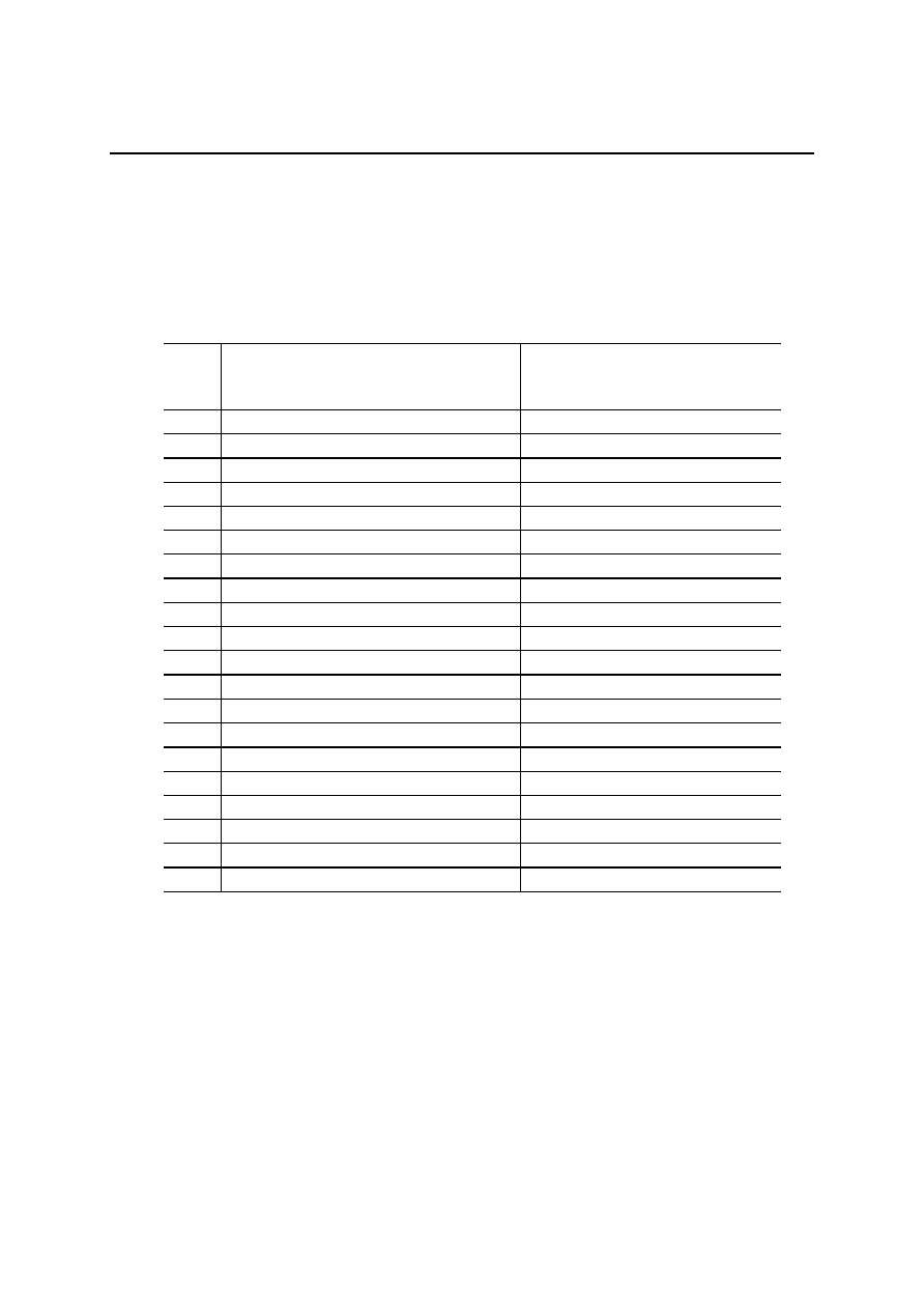
M9800/9836 Connector Pin Layout
Pin No.
When evaluating MSM9802/03/05
(xxx) represents a physical pin name
(Left: STD mode/Right: CPU mode)
When evaluating MSM9836
(xxx) represents a physical pin name
1
V
CC
V
CC
2
V
CC
V
CC
3
V
CC
V
CC
4
EXTCPUSTDB (CPU/
STD
)
EXTCPUSTDB (Not applicable)
5
N.C.
BUSYBOUT (
BUSY
)
6
EXTI0 (SW0∑I0)
EXTI0 (I0)
7
EXTI1 (SW2∑I1)
EXTI1 (I1)
8
EXTI2 (SW3∑I2)
EXTI2 (I2)
9
EXTI3 (A0∑I3)
EXTI3 (I3)
10
EXTI4 (A1∑I4)
EXTI4 (I4)
11
EXTI5 (A2∑I5)
EXTI5 (I5)
12
N.C.
EXTI6 (I6)
13
N.C.
N.C.
14
EXTRESTB (
RESET
)
EXTRESTB (
RESET
)
15
EXTSTB (Not applicable∑
ST
)
EXTSTB (
ST
)
16
N.C.
N.C.
17
NAROUT (
BUSY
∑NAR)
NAROUT (NAR)
18
GND
GND
19
GND
GND
20
GND
GND
Note 1: 1-3 pins of this connector output +5 V. Short circuit with power supply circuit of the external
unit may cause damage of the power supply unit and/or the evaluation board.
(
The
connector's 1 - 3 pins should be cut and isolated, as required.
)
Note 2: Every input pin is either pulled-up or pulled-down with a resistor. Be aware that not every pin
function identically to those on your target device, MSM9802/03/05/36.
FEBL9800-03
1Semiconductor
MSM9800/9836 EVA Board
5/15
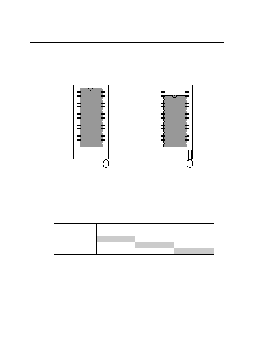
Evaluation ROM Socket
Use this socket to mount an EPROM containing sound data for evaluation. When using a 512 Kbit EPROM,
place the chip so that the pin 14 is inserted to the socket's pin 16 position, as shown in the figure below.
Use EPROM Size Selector Switches to select a proper EPROM size.
EPROM Size Selector Switches
The following table shows the selector switch position for each EPROM size.
EPROM Size
2M/4M Selector
1M/4M Selector
512K/4M Selector
4 Mbit
4Mbit Side
4 Mbit Side
4 Mbit Side
2 Mbit
2 Mbit Side
4 Mbit Side
4 Mbit Side
1 Mbit
4 Mbit Side
1 Mbit Side
4 Mbit Side
512 Kbit
4 Mbit Side
4 Mbit Side
512 Kbit Side
* Use an EPROM of equal or larger size than the target device's on-chip ROM.
Control Selector Switches
Target Device Selector Switches
M9805 side: To evaluate sound data for use with MSM9802/03/05.
M9836 side: To evaluate sound data for use with MSM9836.
EXT/INT Selector Switch
EXT side:
To control MCU IF/Stand-alone mode switching and phrase triggering from an external
MCU via 20-pin connector.
INT side:
To control MCU IF/Stand-alone mode switching and phrase triggering by using on-board
CPU/STD Selector and Phrase Selector/Trigger Key Pad.
Mounting position for a 4 Mbit, 2 Mbit
or 1 Mbit EPROM
Mounting position for a 512 Kbit
EPROM
TEXTOOL
TEXTOOL