 | –≠–ª–µ–∫—Ç—Ä–æ–Ω–Ω—ã–π –∫–æ–º–ø–æ–Ω–µ–Ω—Ç: OL3315L | –°–∫–∞—á–∞—Ç—å:  PDF PDF  ZIP ZIP |
JOG-
JOG-00960
OKI Electronics Components
Rev. 1[03. 2002]
OL3315L
Preliminary
1.3um directly modulated DFB-LD module with an laser diode driver for 10Gb/s
Drawing No.: JOG-00960
OL3315L
Page 1 of
5
Oki Electric Industry Co., Ltd.
1. DESCRIPTION
The OL3315L DFB LD module is a 1310nm, InGaAsP/InP laser diode coupled to a single mode
fiber with a pigtail. The laser chip is driven by a built-in laser diode driver.
2. FEATURES
∑
1310nm DFB-LD
∑
Integrated Laser Diode Driver (LDD)
∑
Built-in Thermistor
∑
Butterfly-like Package
∑
RF Leads on the Opposite Side of a Fiber Pigtail
∑
Pigtail type
3. APPLICATION
∑
10Gb/s transmission
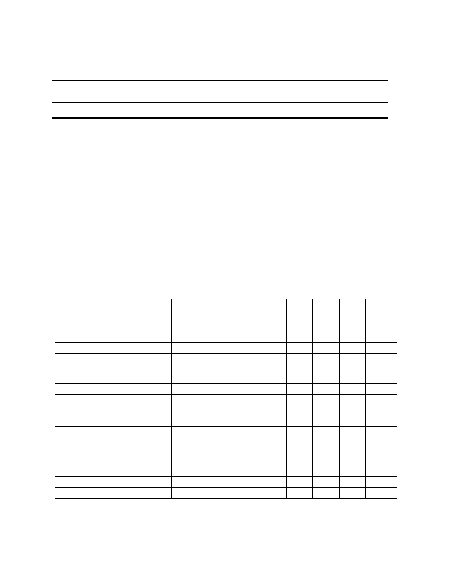
4.OPTICAL AND ELECTRICAL CHARACTERISTICS
(T = 0 to 70∞C, unless otherwise specified)
Parameter
Symbol
Test Conditions
Min. Typ. Max.
Unit
Fiber Output Power
P0
CW
1
mW
Center Wavelength
c
P0 = 1mW
1290
1330
nm
Spectral Width
P0 = 1mW,-20dB
1
2
nm
Side Mode Suppression Ratio
SMSR
P0 = 1mW
30
dB
Monitor Current
Im
P0 =
1mW(RT/SOL)
100
2000
µ
A
Tracking Error
TER
(RT to WCT)
-1.5
+1.5
dB
Photodiode Dark Current
ID
V
R
= 2.2V
1
µ
A
Photodiode Capacitance
Ct
V
R
= 2.2V, f=1MHz
20
pF
LDD Power Supply Voltage
V
EE
-
-5.5
-5.2 -4.75
V
LDD Power Supply Current
I
CC
-
340
mA
Modulation Sensing Resistor
R
MOD
-
2.7
3
3.3
MODEN Bar Input High
V
IH
-
V
EE
+
2.0
V
MODEN Bar Input Low
V
IL
-
V
EE
+
0.8
V
Bias Sensing Resistor
R
BIAS
-
2.7
3
3.3
Differential Input Swing
V
ID
AC-Coupled
0.3
1.6
V
P-P
JOG-00960
OKI Electronics Components
OL3315L
.
Drawing No.: JOG-00960
OL3315L
Page 2of
5
Oki Electric Industry Co., Ltd.
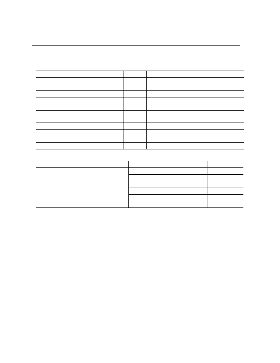
5.ABSOLUTE MAXIMUM RATING
(Ta = 25∞C, unless otherwise specified)
Parameter
Symbol
Rating
Unit
PD Forward Current
I
F
50
mA
PD Reverse Current
I
R
3
mA
PD Reverse Voltage
V
R
15
V
LDD Power Supply Voltage
V
EE
-6.0 to +0.5
V
DATA+, DATA-
-
-1.2 to +0.5
V
MODENB, BIASMON, MODMON,
PWC+, and PWC-
-
V
EE
-0.5 to 0.5
V
MODSET, BIASSET
-
V
EE
-0.5 to V
EE
+1.5
V
Operating Ambient Temperature
Ta
0 to 70
∞
C
Storage Temperature
Tstg
0 to 85
∞
C
Lead Soldering Temperature (10s)
-
260
∞
C
6. CONNECTOR AND FIBER SPECIFICATIONS
Parameter
Specifications
Unit
1.31
µ
m Single Mode Fiber
-
Code Diameter:0.9
mm
Bending Radius: 20 (min)
mm
Heat-resistant
-
Fiber
Length :1000 +/-200
mm
Connector
SC-PC
-

JOG-00960
OKI Electronics Components
OL3315L
.
Drawing No.: JOG-00960
OL3315L
Page 3of
5
Oki Electric Industry Co., Ltd.
7.OUTLINE DRAWING
All dimensions in millimeters
Package No. (Unit: mm)
JOG-00960
OKI Electronics Components
OL3315L
.
Drawing No.: JOG-00960
OL3315L
Page 4of
5
Oki Electric Industry Co., Ltd.
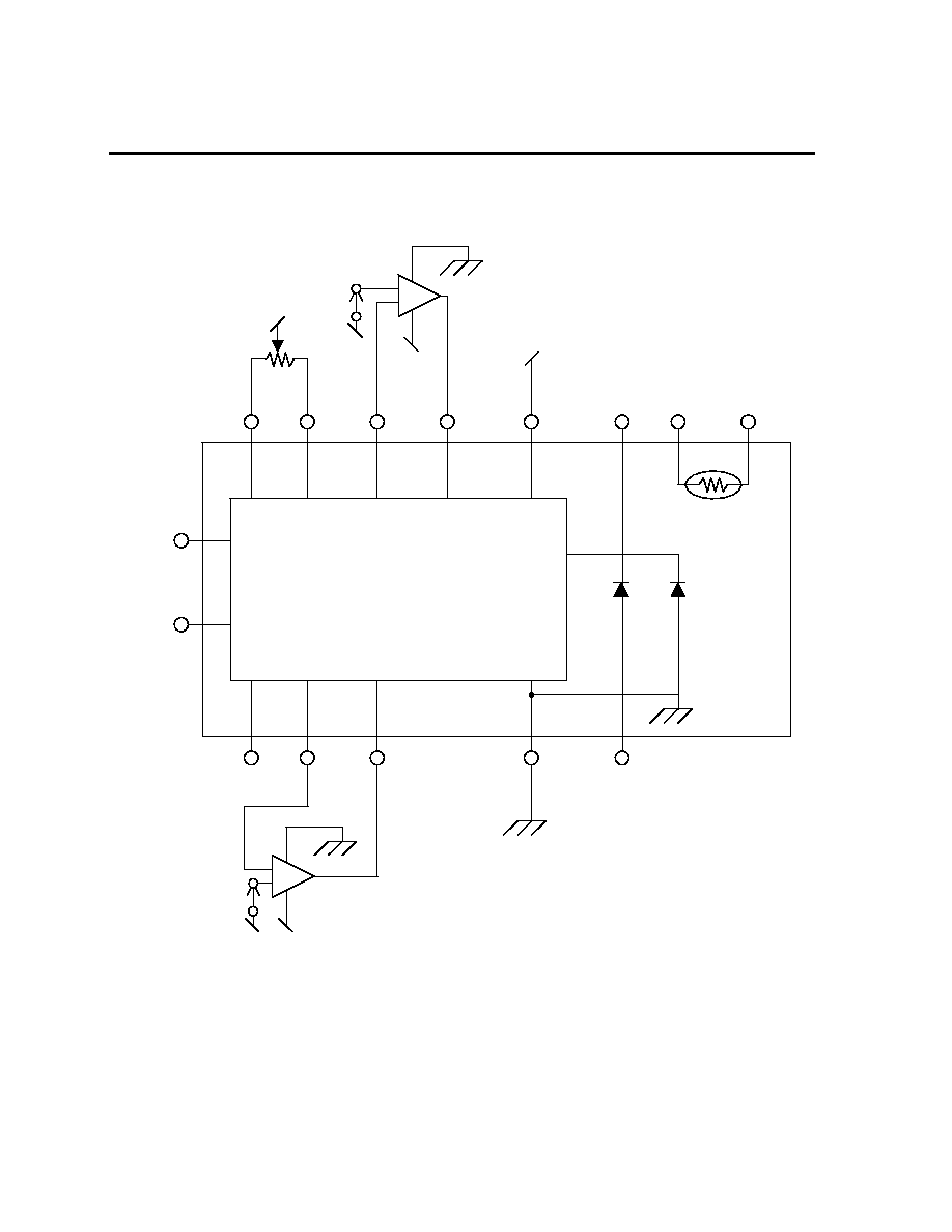
8.Diagram
DFB LD
PD
Thermistor
Thermistor
Thermistor
PD
Cathode
PD
Anode
DATA+
DATA-
BIASSET
BIASMON
PWC-
PWC+
MODEN Bar
MODMON
MODSET
Laser Diode Driver
GND
VEE
VEE
VEE
VEE
V
BIAS
+
-
VEE
VEE
V
MOD
-
+
VEE
R
PWC

JOG-00960
OKI Electronics Components
OL3315L
.
Drawing No.: JOG-00960
OL3315L
Page 5of
5
Oki Electric Industry Co., Ltd.
Pin Description
Name
Function
DATA+
Noninverting Data Input.
DATA-
Inverting Data Input.
V
EE
Power Supply Voltage.
PWC+
Positive Input for Modulation Pulse-Width Adjustment. Connected to V
EE
through R
PWC
(See DIAGRAM). When PWC+ and PWC- are left open, the
pulse-width controll circuit is automatically disabled.
PWC-
Negative Input for Modulation Pulse-Width Adjustment. Connected to V
EE
through R
PWC
(See DIAGRAM). When PWC+ and PWC- are left open, the
pulse-width controll circuit is automatically disabled.
MODEN Bar
Negative TTL/CMOS Modulation Enable Input. Low for enabled
modulation, high to disable the modulation.
MODMON
Modulation Current monitor. I
MOD
=(V
MODMON
-V
EE
)/R
MOD
MODSET
Modulation Current Set. Connected to the output of the external
operationalamplifier (See DIAGRAM).
BIASMON
Bias Current monitor. I
BIAS
=(V
BIASMON
-V
EE
)/R
BIAS
BIASSET
Bias Current Set. Connected to the output of the external
operationalamplifier (See DIAGRAM).
Copyright 2001 Oki Electric Industry Co., Ltd.