
OL4121N-120 and OL4121N-140
High-Power Laser Diode Butterfly Modules
(1480 nm, 120 mW/140 mW)
February 2000
O K I F I B E R - O P T I C P R O D U C T S
D
ATA
S
HEET

s
s
≠≠≠≠≠≠≠≠≠≠≠≠≠≠≠≠≠≠≠≠≠≠≠≠≠≠≠≠≠≠≠≠≠≠≠≠≠≠≠≠≠≠≠≠≠≠≠≠≠≠≠≠≠≠≠≠≠≠≠≠≠≠≠≠≠≠≠≠≠≠≠≠≠≠≠≠≠≠≠≠≠≠≠≠≠≠≠≠≠≠≠
Oki Semiconductor
CONTENTS
OL4121N-120 and OL4121N-140 High-Power Laser Diode Butterfly Modules
...... 1
1
Oki Semiconductor
OL4121N-120 and OL4121N-140
High-Power Laser-Diode Butterfly Modules
INTRODUCTION
Oki Semiconductor's OL4121N-120/OL4121N-140 family of 1480-nm high-power laser diodes are avail-
able in a 14-pin "butterfly" package which is designed for high-performance fiber-optic applications. The
OL4121N-120 and OL4121N-140 diodes have a built-in thermo-electric cooler, thermistor, and isolator,
and have a single-mode fiber pigtail.
The OL4121N is available in two optional power levels: 120 mW or 140 mW. These laser diodes can be
used as a pumping source for an Er- (erbium) doped fiber-optic amplifier. The high power output of the
laser diodes in the OL4121N family supports the high-performance demands of Erbium-Doped Fiber-
optic Amplifiers in Dense Wavelength Division Multiplex (DWDM-EDFA) systems and long-haul terres-
trial networks.
FEATURES
∑ High power output: Pf=120 mW (OL4121N-120)
Pf=140 mW (OL4121N-140)
∑ 14-pin "butterfly" package
∑ Single-mode fiber
∑ Built-in isolator
∑ Includes photodiode for power monitoring
∑ Built-in thermo-electric cooler (TEC)
APPLICATION
∑ WDM/DWDM systems
∑ Erbium-doped fiber amplifier
∑ Regeneration of data
∑ Fiber-optic long-haul terrestrial networks
s
OL4121N-120 and OL4121N-140
s
≠≠≠≠≠≠≠≠≠≠≠≠≠≠≠≠≠≠≠≠≠≠≠≠≠≠≠≠≠≠≠≠≠≠≠≠≠≠≠≠≠≠≠≠≠≠≠≠≠≠≠≠≠≠≠≠≠≠≠≠≠≠≠≠
2
Oki Semiconductor
ELECTRICAL CHARACTERISTICS
Exceeding these maximum ratings could cause immediate damage or lead to permanent deterioration of the device.
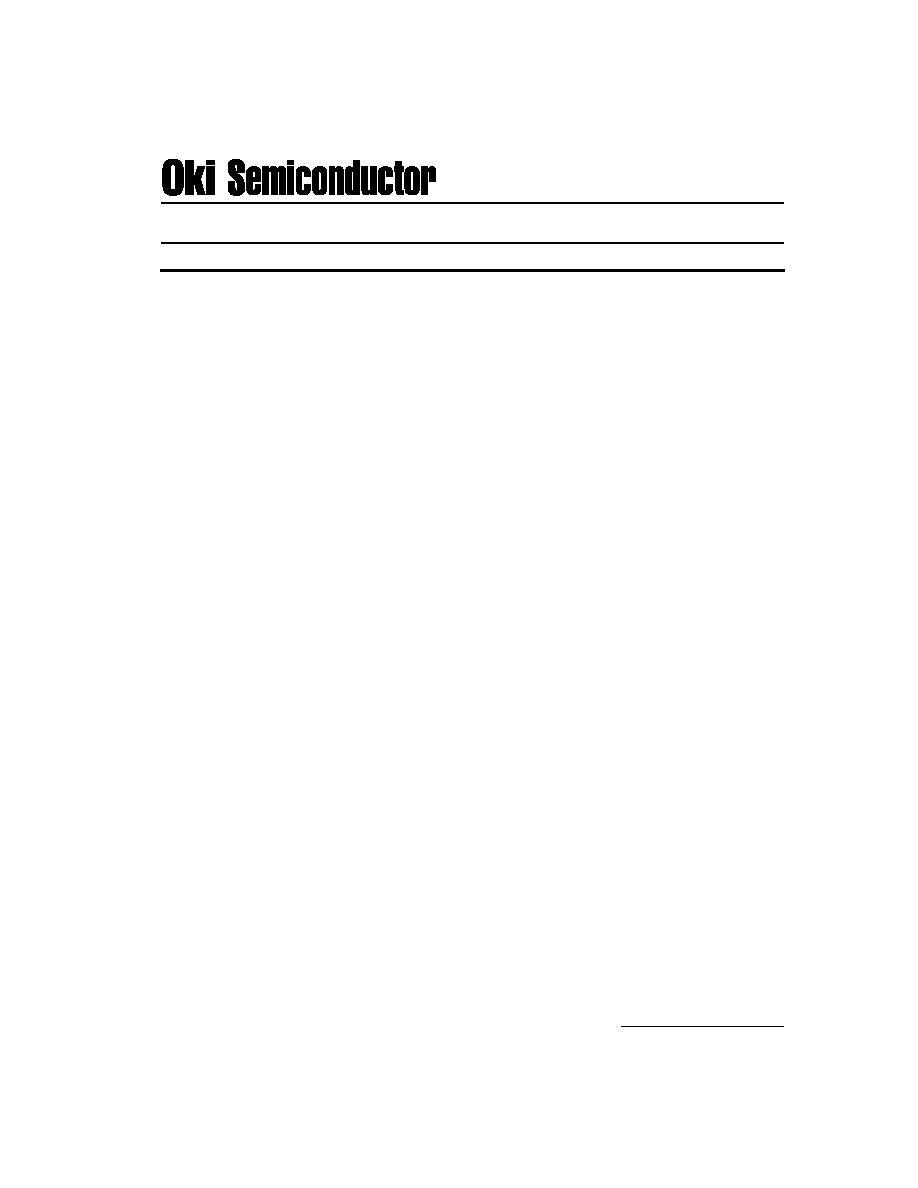
Absolute Maximum Ratings (ambient temperature Ta = 25∞C unless otherwise noted)
Parameter
Symbol
Ratings
Units
Fiber Output Power
OL4121N-120
Pf
130
mW
OL4121N-140
160
mW
Laser Diode Forward Current
OL4121N-120
I
F(LD)
750
mA
OL4121N-140
800
mA
Laser Diode Reverse Voltage
V
R(LD)
2
V
Photo Diode Reverse Voltage
V
R(PD)
15
V
Operating Temperature Range
Topr
-20 to +65
∞C
Storage Temperature Range
Tstg
-40 to +70
∞C
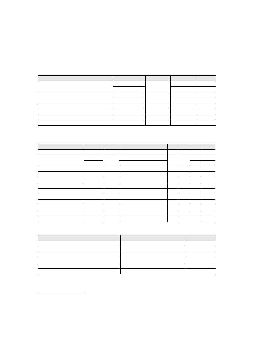
Optical and Electrical Characteristics (Ta = 25∞C)
Parameter
Symbol
Test Conditions
Min.
Typ.
Max.
Units
Threshold Current
I
TH
---
---
---
60
mA
Laser Diode Operating Current
OL4121N-120
Iop
(LD)
Pf = 120 mW
---
---
600
mA
OL4121N-140
Pf = 140 mW
700
mA
Laser Diode Operating Voltage
Vop
(LD)
Pf = 120 / 140 mW
---
---
2.5
V
Center Wavelength
c
Pf = 120 / 140 mW
1460
---
1490
nm
RMS Spectral Width
Pf = 120 / 140 mW (RMS)
---
---
10
nm
Tracking Error
TER
I
M
= const., 0/ 25/ 65∞C
---
---
+/-1.0
dB
PD Dark Current
I
DARK
V
R(PD)
= 5 V
---
---
100
nA
Monitor Current
Im
Pf = 120 / 140 mW, V
R(PD)
= 5 V
100
---
---
µ
A
Thermoelectric Cooler Capacity
T
Pf = 120 / 140 mW
40
---
---
∞C
Thermoelectric Cooler Current
I
TEC
T = 40∞C, Pf = 120 / 140 mW
---
---
1.5
A
Thermoelectric Cooler Voltage
V
TEC
T = 40∞C, Pf = 120 / 140 mW
---
---
4.0
V
Thermistor Resistance
Rth
---
9
---
11
K
Fiber Pigtail Specifications
Parameter
Specifications
Units
Type
SM
---
Mode Field Diameter
10 +/-1
µ
m
Cladding Diameter
125 +/-2
µ
m
Jacket Diameter
900
µ
m
Length
1.0 (Minimum)
m
Connector
FC
---
≠≠≠≠≠≠≠≠≠≠≠≠≠≠≠≠≠≠≠≠≠≠≠≠≠≠≠≠≠≠≠≠≠≠≠≠≠≠≠≠≠≠≠≠≠≠≠≠≠≠≠≠≠≠≠≠≠≠≠≠≠≠≠
s
OL4121N-120 and OL4121N-140
s
3
Oki Semiconductor
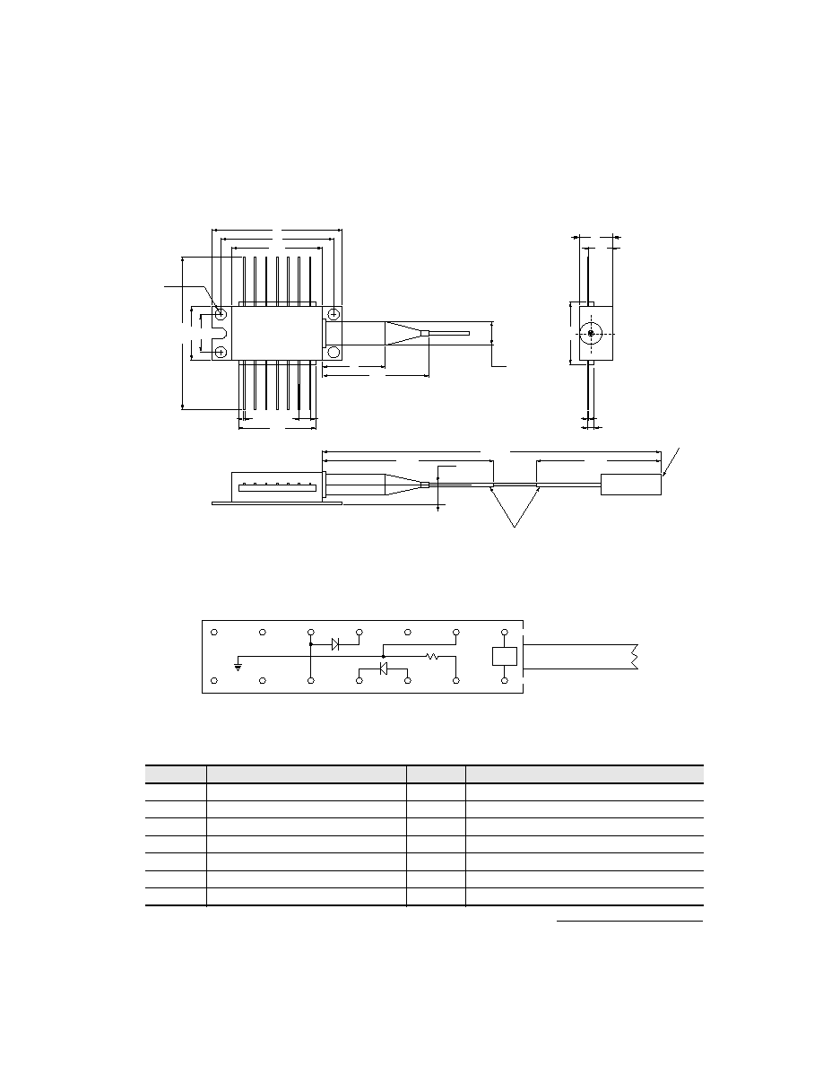
PACKAGE DIMENSIONS
(Units: mm)
Pin Configuration
Pin No.
Description
Pin No.
Description
01
Thermo Electric Cooler (+)
08
NC
02
Thermistor 09
NC
03
PD Anode
10
LD Anode
04
PD Cathode
11
LD Cathode
05
LD Anode
12
NC
06
NC
13
Thermistor and Case Ground
07
NC
14
Thermo Electric Cooler Cathode (-)
36 (min.)
12.7
20.83
280
±
10
50
±
20
26
30
0.35
±
0.2
d = 2.6
0.2
±
0.1
1.52
5.4
2.54
26
±
1
16
17.78
8.9
5.6
8
∞
Angled ¯2.5mm
Ferrule
¯0.9mm Loose Tube
5.1
1100 (min.)
14.7
8.0
0.25 ± 0.1
1000 (min.)
0.48 ± 0.2
Tolerance = ±0.5 mm (unless noted otherwise)
5.35
T.E.C
LD
PD
TH
#14
#13
#11
#10
#1
#2
#4
#5
#3
(-)
(+)
FIBER
TH:
T.E.C:
Thermo-Electric Cooler
Thermistor
TERMINAL CONNECTION (BOTTOM VIEW)
CASE
#9
#8
#7
#6
#12