Oki Optical Components
OL5155M
1550-nm 40-Gbps EA Modulator with Integrated DFB Laser
1/3
DESCRIPTION
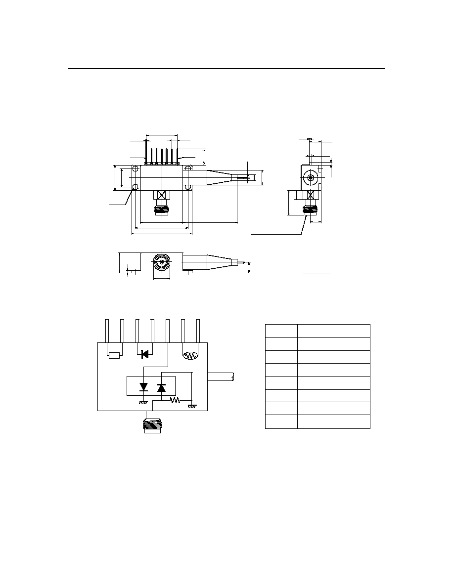
Oki's OL5155M is a 1550-nm DFB laser diode that is monolithically integrated with an electro-
absorption (EA) modulator. The OL5155M is designed for 40-Gbps operation and is available in a
7-pin package with a V-connector.
FEATURES
� High modulation bandwidth : > 30 GHz (- 3 dB electrical)
� Low modulation voltage : < 3.0 Vpp
� Large dynamic extinction ratio @ 40 Gbps : 10 dB (typical)
� Fiber output power : > 3 dBm (CW)
APPLICATION
� 40 Gbps very short reach (< 2 km) data communication
� 40 Gbps NRZ / RZ medium and long reach transmission
OPTICAL AND ELECTRICAL CHARACTERISTICS
(T
LD
= 25�C, Tc = 0
to 65�C, unless otherwise specified)
Parameter
Symbol
Test Conditions
Min. Typ. Max. Unit
Fiber Output Power
Po
CW, Vm = 0V
3
---
---
dBm
Operation Current
Iop
Po = 3dBm, CW, Vm = 0V
---
---
100
mA
Threshold Current
Ith
-----
---
---
35
mA
Peak Wavelength
p
Po = 3dBm
1530
---
1565
nm
Side Mode Suppression Ratio
SMSR
Po = 3dBm
30
---
---
dB
LD Forward Voltage
Vf
Po = 3dBm, CW, Vm = 0V
---
---
2.0
V
Monitor Current Im Po = 3dBm, CW 50 --- 1000
�A
Bandwidth fc - 3dB
(electrical)
, Vm = -1V 30 --- --- GHz
Static Extinction Ratio
ExR
CW, 0 to �3 V
---
14
---
dB
TEC Current
Ipe
T = 40�C, Po = 3dBm
---
---
1.2
A
TEC Voltage
Vpe
T = 40�C, Po = 3dBm
---
---
3
V
Thermistor Resistance
Rth
-----
9.5
---
10.5
k
Thermistor B Value
Bth
25�C/50�C
---
3450
---
K

Oki Optical Components
OL5155M
2/3
ABSOLUTE MAXIMUM RATING
(Tc = 25 �C, unless otherwise specified)
Parameter
Symbol
Rating
Unit
Operating Case Temperature
Tc
0 to +65
�C
Storage Temperature
Tstg
-40 to +85
�C
LD Forward Current
I
LDF
150
mA
LD Reverse Voltage
V
LDR
2
V
Modulator Voltage
V
m
-3.5 to +0.5
V
TEC Voltage
Vc
3.2
V
TEC Current
Ic
1.5
A
CONNECTOR AND FIBER SPECIFICATIONS
Parameter
Specifications
Unit
Type
SMF
---
Mode Field Diameter 10.5+/-1 �m
Cladding Diameter 125+/- 2 �m
Jacket Diameter
0.9
mm
Length
1 (min.)
m
Connector
FC/SPC
---

Oki Optical Components
The information contained herein can change without notice owing to product and/or technical improvements.
Please make sure before using the product that the information you are referring to is up-to-date.
The outline of action and examples of application circuits described herein have been chosen as an explanation of the standard action and performance of the
product. When you actually plan to use the product, please ensure that the outside conditions are reflected in the actual circuit and assembly designs.
Oki Optical Components assumes no responsibility or liability whatsoever for any failure or unusual or unexpected operation resulting from misuse, neglect,
improper installation, repair, alteration or accident, improper handling, or unusual physical or electrical stress including, but not limited to, exposure to parameters
outside the specified maximum ratings or operation outside the specified operating range.
Neither indemnity against nor license of a third party's industrial and intellectual property right,etc.is granted by us in connection with the use of product and/or the
information and drawings contained herein. No responsibility is assumed by us for any infringement of a third party's right which may result from the use thereof.
When designing your product, please use our product below the specified maximum ratings and within the specified operating ranges, including but not limited to
operating voltage, power dissipation, and operating temperature.
The products listed in this document are intended for use in general electronics equipment for commercial applications (e.g., office automation, communication
equipment, measurement equipment, consumer electronics, etc.). These products are not, unless specifically authorized by Oki, authorized for use in any system or
application that requires special or enhanced quality and reliability characteristics nor in any system or application where the failure of such system or application
may result in the loss or damage of property, or death or injury to humans.
Certain parts in this document may need governmental approval before they can be exported to certain countries. The purchaser assumes the responsibility of
determining the legality of export of these parts and will take appropriate and necessary steps, at their own expense, for export to another country.
Copyright 2002 Oki Optical Components
Oki Optical Components reserves the right to make changes in specifications at anytime and without notice. This information furnished by Oki Optical Components
in this publication is believed to be accurate and reliable. However, no responsibility is assumed by Oki Optical Components for its use; nor for any infringements of
patents or other rights of third parties resulting from its use. No license is granted under any patents or patent rights of Oki Optical Components.