Document Outline
- First Page
- Ordering Information
- Specifications
- Dimensions
- Hints on Correct Use
- Contact Omron
Part number
Accessory
Light gray
Black
End cap
A7B-M
A7B-M-1
Spacer
A7B-PA
A7B-PA-1
Connector
Solder terminal
A7B-C
A7B-C
PCB terminal
A7B-CP
A7B-CP
Reliable Thumbwheel Switch with Dustproof
Construction and Easy Front Mounting
I
Locking switches cut down operating errors
in control panels
I
Internal contacts boost reliability
Ordering Information
I
SWITCH UNITS
Part number
Solder terminal
Output code
Type
Light gray case
Black case
06 (binary code)
Locking
A7BL-206
A7BL-206-1
07 (binary code w/diode provision)
Locking
A7BL-207
A7BL-207-1
Note: Switch units, end caps, spacers, and connectors must be ordered separately and are not factory-assembled for shipment.
I
ACCESSORIES
To order spacers marked with measurement units or symbols, select the unit or symbol from the table below and put its code
letter in place of the final letter A in the model number.
Example: A7B-PK (light gray spacer with
∞
C mark for A7BL)
Code letter
A
B
C
D
E
F
G
H
J
K
L
Q
T
U
Marking
Blank
SEC
MIN
H
g
kg
mm
cm
m
∞
C
PCS
x10 SEC
0
∑
Thumbwheel Switch
A7BL
Note: A7BL switch units can be ordered with limited setting ranges. When ordering, include
the range in the model number as shown in the following examples:
A7BL-206-S06 (Light gray A7BL with a range of 0 to 6)
A7BL-206-S18-1 (Black A7BL with a range of 1 to 8)
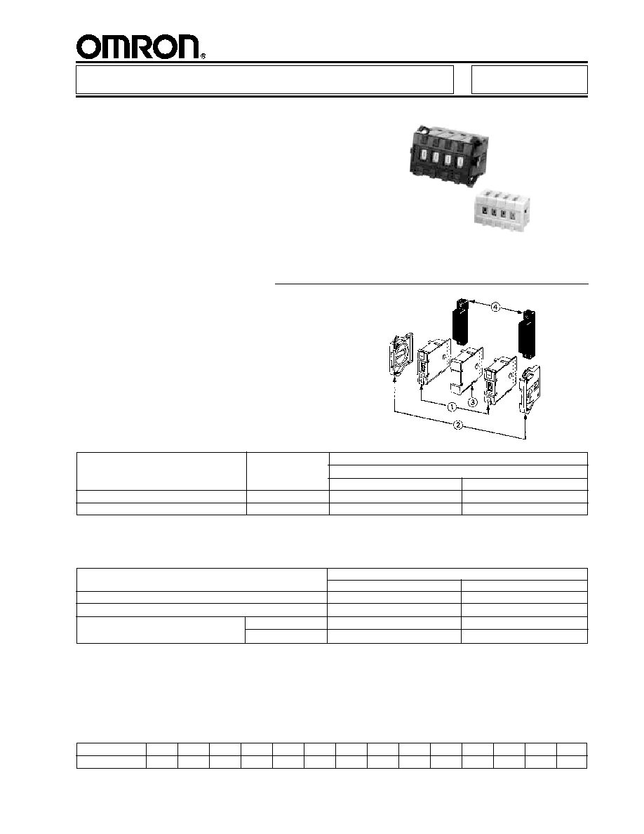
1. Switch units
2. End caps
3. Spacer
4. Connectors
Note: 1. When placing your order, please specify the model numbers and quantities of required switch units, end caps, and spacers,
respectively. (Note that switch units and accessories are not factory-assembled for shipment.)
2. End caps come as a set, left and right.
213

A7BL
214
A7BL
Specifications
Dimensions
Unit: mm (inch)
Note: 1. Unless otherwise specified, a tolerance of
±
0.4 mm
applies to all dimensions.
2. Each model number applies to a single switch unit and
not to the switch assembly as shown in the drawings.
3. Common terminal "C" is at the bottom when the switch
is viewed from the front.
4. The asterisk "*" indicates a dimension of 32.5 mm for a
switch unit with an output code pf 06 and 43.5 mm for
one with an output code of 07.
Switching capacity
50 VAC/28 VDC, 1 mA to 0.1A (resistive load)
Carry current
1 A max.
Contact resistance
200 m
max.
Insulation resistance
10 M
min. (at 500 VDC) between
nonconnected terminals
1,000 M
min. (at 500 VDC) between
each terminal and noncurrent carrying part
Dielectric strength
600 VAC, 50/60 Hz for 1 minute
between nonconnected terminals
1,000 VAC, 50/60 Hz for 1 minute between each terminal and noncurrent carrying part
Operating force
550 g max.
Vibration resistance
10 to 55 Hz, 1.5 mm double amplitude
Shock resistance
500 m/s
2
(approx. 50 G) min.
Ambient temperature
-10
∞
to 65
∞
C (no condensation)
Storage temperature
-20
∞
to 80
∞
C
Humidity
45% to 85%
Service life
Mechanical
100,000 steps min.
Electrical
50,000 steps min.
Weight (per unit)
Approx. 4.1 g
Note: Data shown are of initial value
I
CHARACTERISTICS
I
LOCKING SWITCHES
A7BL-206(206-1)
A7BL-207(207-1)
Number of
A
B
C
units (n)
(n x 8 + 8)
(n x 8 + 6)
1
16 (0.60)
14 (0.60)
14.4 (0.57)
2
24 (0.90)
22 (0.90)
22.4 (0.88)
3
32 (1.30)
30 (1.20)
30.4 (1.20)
4
40 (1.60)
38 (1.50)
38.4 (1.50)
5
48
±
0.8 (1.9
±
0.03)
46
±
0.8 (1.8
±
0.03)
46.8 (1.80)
6
56
±
0.8 (2.2
±
0.03)
54
±
0.8 (2.1
±
0.03)
54.8 (2.20)
7
64
±
0.8 (2.5
±
0.03)
62
±
0.8 (2.4
±
0.03)
62.8 (2.50)
8
72
±
0.8 (2.8
±
0.03)
70
±
0.8 (2.7
±
0.03)
70.8 (2.80)
9
80
±
0.8 (3.1
±
0.03)
78
±
0.8 (3.0
±
0.03)
78.8 (3.10)
10
88
±
0.8 (3.5
±
0.03)
86
±
0.8 (3.4
±
0.03)
86.8 (3.40)
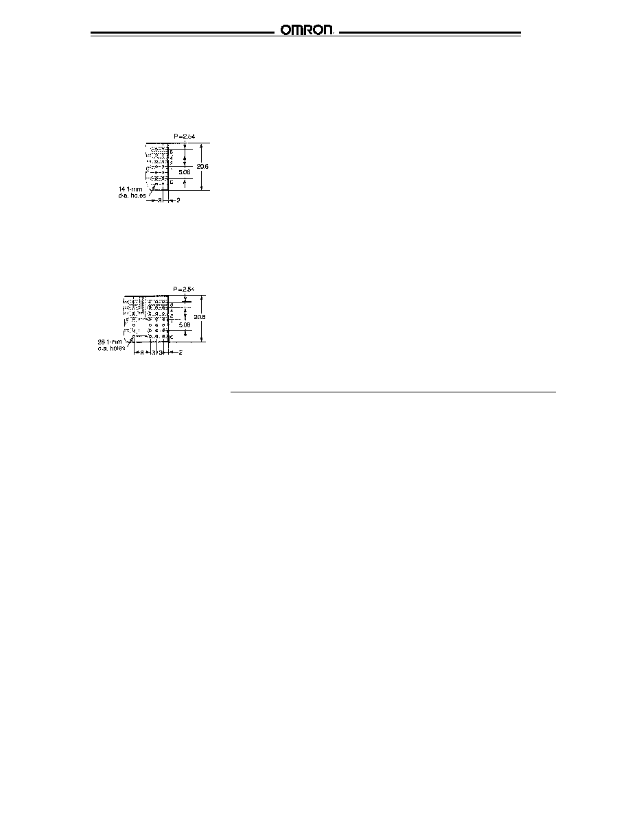
Panel cutout

215
A7BL
A7BL
I
END CAPS
A7B-M(-M-1)
Note: Unless otherwise specified, a tolerance of
±
0.4 mm applies to all dimensions
(left side)
(right side)
I
SPACERS
A7B-PA(-PA-1)
I
CONNECTORS
A7B-C (for solder terminals)
A7B-C (for PCB terminals)
Note: Unless otherwise specified, a tolerance of
±
0.4 mm applies to all dimensions
A7BL
216
A7BL
I
TERMINALS
Hints on Correct Use
Refer to HINTS ON CORRECT USE under the General Information section.
A7BL
Solder terminals
06 Output code
07 Output code
A7BL
Solder terminals

OMRON ELECTRONICS LLC.
OMRON CANADA, INC.
One East Commerce Drive
885 Milner Avenue
Schaumburg, IL 60173
Scarborough, Ontario M1B 5V8
1-800-55-OMRON
416-286-6465
Cat. No. GC SW6 04/01 Specifications subject to change without notice. Printed in the U.S.A.
NOTE: DIMENSIONS ARE SHOWN IN MILLIMETERS. To convert millimeters to inches divide by 25.4.
OMRON ON-LINE
Global - http://www.omron.com
USA - http://www.omron.com/oei
Canada - http://www.omron.com/oci
A7BL
A7BL