Document Outline
- Low-torque Basic Switch D2MC
- Ordering Information
- Specifications
- Ratings
- Characteristics
- Approved Standards
- Operating Characteristics
- Engineering Data
- Dimensions
- Accessories (Order Separately)
- Precautions
138
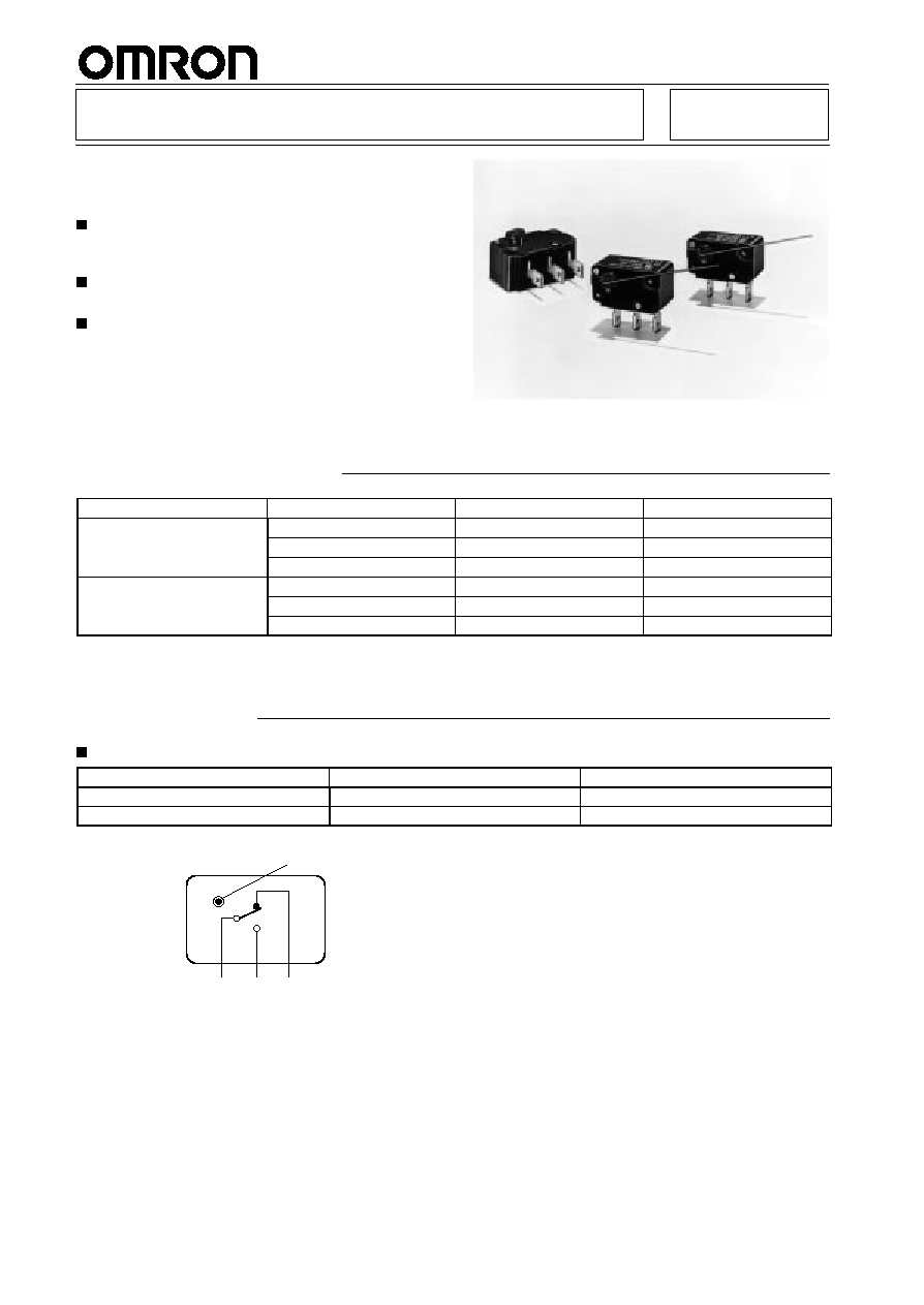
Low-torque Basic Switch
D2MC
Highly Reliable Rotary-action Switch for
Low Torque Operation
0.5 A rated model (D2MC-01
j
) employs crossbar
alloy #1 contacts which exhibit unsurpassed
contact reliability in very small load ranges.
High-capacity 5 A Model (D2MC-5
j
) employs
silver contacts.
Long life (10,000,000 mechanical operations min.)
through use of a movable coil spring.
Ordering Information
Direction of actuation
OF
5 A
0.5 A
Clockwise
5.1 g
S
cm max.
D2MC-5E
D2MC-01E
7.6 g
S
cm max.
D2MC-5F
D2MC-01F
10.2 g
S
cm max.
D2MC-5H
D2MC-01H
Counterclockwise
5.1 g
S
cm max.
D2MC-5EL
D2MC-01EL
7.6 g
S
cm max.
D2MC-5FL
D2MC-01FL
10.2 g
S
cm max.
D2MC-5HL
D2MC-01HL
Note:
All the models listed here are supplied without actuator lever. If an actuator lever is required, please order separately by indicating the
model name of the actuator lever.
See
Accessories.
Specifications
Ratings
Item
D2MC-5
j
D2MC-01
j
Electrical ratings
5 A at 125/250 VAC (resistive load)
0.5 A t 125VAC/30 VDC (resistive load)
Inrush current
NC: 15 A; NO: 7 A
0.5 A
Contact Form
COM
NO
NC
D2MC
D2MC
139
Characteristics
Item
D2MC-5
j
D2MC-01
j
Operating speed
1
�
to 360
�
/sec
Operating frequency
Mechanical: 240 operations/min
Electrical:
20 operations/min
Mechanical: 240 operations/min
Electrical:
60 operations/min
Insulation resistance
100 M
min. (at 500 VDC)
Contact resistance
20 m
max. (initial value)
100 m
max. (initial value)
Dielectric strength
600 VAC, 50/60 Hz for 1 min between non-continuous terminals
1,500 VAC, 50/60 Hz for 1 min between current-carrying metal parts and ground, and between each
terminal and non-current-carrying metal part
Vibration resistance
Malfunction: 10 to 55 Hz, 1.5-mm double amplitude
Shock resistance
Destruction: 1,000 m/s
2
(approx. 100G)
Malfunction: D2MC-
j
E: 100 m/s
2
(approx. 10G)
D2MC-
j
F: 100 m/s
2
(approx. 10G)
D2MC-
j
H: 200 m/s
2
(approx. 20G)
Life expectancy
Mechanical: 10,000,000 operations min.
Electrical:
100,000 operations min.
Mechanical: 10,000,000 operations min.
Electrical:
100,000 operations min. (1,000,000
operations at 0.1 A, 125 VAC/30 VDC)
Ambient temperature
Operating: �25
�
C to 80
�
C (with no icing)
Ambient humidity
Operating: 85% max.
Weight
Approx. 10.5 g
Note:
All the models listed here are supplied without actuator lever. If an actuator lever is required, please order separately by indicating the
model name of the actuator lever.
See
"Accessories".
Approved Standards
UL (File No. E41515)
CSA (File No. LR21642)
D2MC-5
j
series: 5 A, 125 VAC
5 A, 250 VAC
D2MC-01
j
series: 0.5 A, 125 VAC
0.5 A, 30 VDC
Operating Characteristics
Model
D2MC-
j
E
D2MC-
j
F
D2MC-
j
H
OF max.
0.5 mN
S
m (5.1 gf
S
cm)
0.75 mN
S
m (7.6 gf
S
cm)
1.0 mN
S
m (10.2 gf
S
cm)
RF min.
0.05 mN
S
m (0.6 gf
S
cm)
0.09 mN
S
m (0.9 gf
S
cm)
0.13 mN
S
m (1.3 gf
S
cm)
PT max.
21
�
OT min.
17
�
MD min.
3
�
RT min.
5
�
TT min.
38
�
FP
15
�
3
�
D2MC
D2MC
140
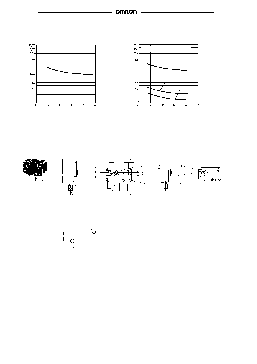
Engineering Data
Mechanical Life Expectancy
Electrical Life Expectancy
Overtravel (mm)
Switching current (A)
Number of operations (x10 )
3
Number of operations (x10 )
3
Without load
Operating frequency: 240 operations/minute
Overtravel (deg)
Operating frequency: 20 operations/minute
0.1 A 125 VAC
0.5 A 125 VAC
5 A 250 VAC
Dimensions
Note:
1. All units are in millimeters unless otherwise indicated.
2. Unless otherwise specified, a tolerance of
�
0.4 mm applies to all dimensions.
Snap-on Mounting
Counterclockwise
Mounting Holes
Two 3.1 dia. mounting
holes or M3 screw holes
23.8
�
0.1
8.7
�
0.1
31
#205 series quick connect
terminals (0.8 t)
18.2
17
14.1
10
27.8
17.5
FP
PT
OT
9
9
5
0.8
2
3.6
8.7
�
0.1
3.1
�
0.05
4
�
0.1 dia.
0.8
Operating
direction
3.1
�
0.05 dia.
3.6
23.8
�
0.1
18
�
0.1
19.3
PT
FP
OT
Clockwise
D2MC
D2MC
141
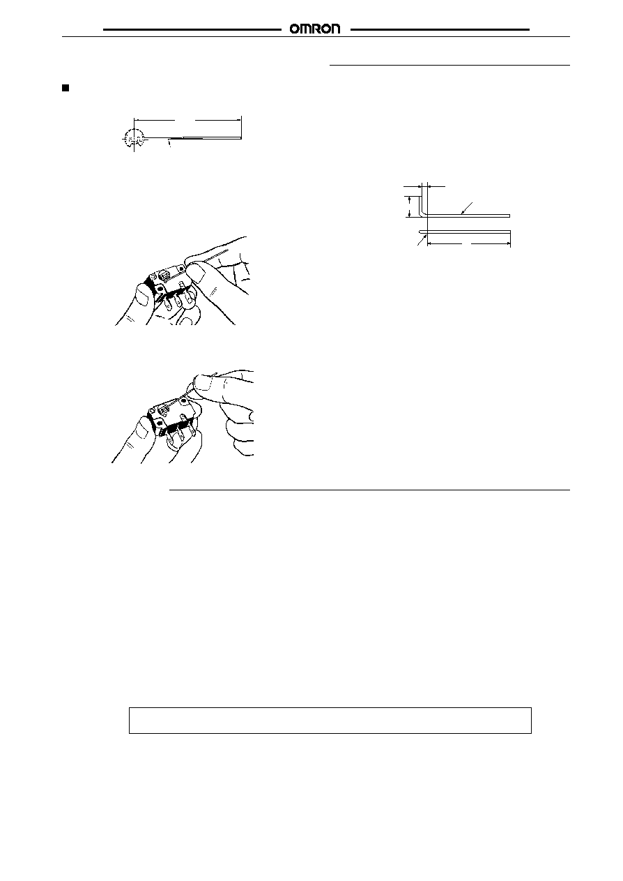
Accessories (Order Separately)
Actuator Lever
CAA1M for Snap-on Mounting
0.6 dia. stainless steel wire
50
�
1
In addition to the standard wire lever model shown here, various
other levers are available upon request.
Mounting Actuator Lever
1. Insert the end of the actuator lever into the hole in the rotary
disc.
2. Push the lever down in the direction of the groove in the rotary
disc.
Designing Own Actuator
If you decide to make your own actuator lever, the materials used
should be stainless steel, piano wire, hard aluminum wire, etc.
There are no restrictions on the tip shape or length of the actuator
lever. However, if the lever is too long, improper switch resetting or
contact chattering may occur. Therefore, the shape of lever as
shown below is suitable.
0.6 dia. stainless steel wire
Center of
rotating axis
1.6
3.6
l
The appropriate value of dimension (
l
) from the fulcrum is 50 mm.
Precautions
Mounting/Soldering
Use M3 mounting screws with plain washers or spring washers to
mount the switch. Tighten the screws to a torque of 3 kg
S
cm
(0.29 N
S
m).
When soldering a lead wire to a terminal of the D2MC, use a solder-
ing iron with a maximum capacity of 60 W and do not take more than
5 s to solder the lead wire, otherwise the characteristics of the
D2MC may be altered.
Applying a soldering iron for too long a time or using one that is rated
at more than 60 W may degrade the switch characteristics.
Do not change the operating position by modifying the actuator.
Microvoltage/current Load
For details, refer to
"General Information".
ALL DIMENSIONS SHOWN ARE IN MILLIMETERS.
To convert millimeters into inches, multiply by 0.03937. To convert grams into ounces, multiply by 0.03527.
Cat. No. B51-E1-6