 | –≠–ª–µ–∫—Ç—Ä–æ–Ω–Ω—ã–π –∫–æ–º–ø–æ–Ω–µ–Ω—Ç: D2SW-3T | –°–∫–∞—á–∞—Ç—å:  PDF PDF  ZIP ZIP |
Document Outline
- Watertight Miniature Basic Switch
- Ordering Information
- Specifications
- Ratings
- Approved Standards
- Contact
- Characteristics
- Operating Characteristics
- Dimensions
- Terminal Model
- Lead Wire Model
- Kind of Terminals
- Precautions
127
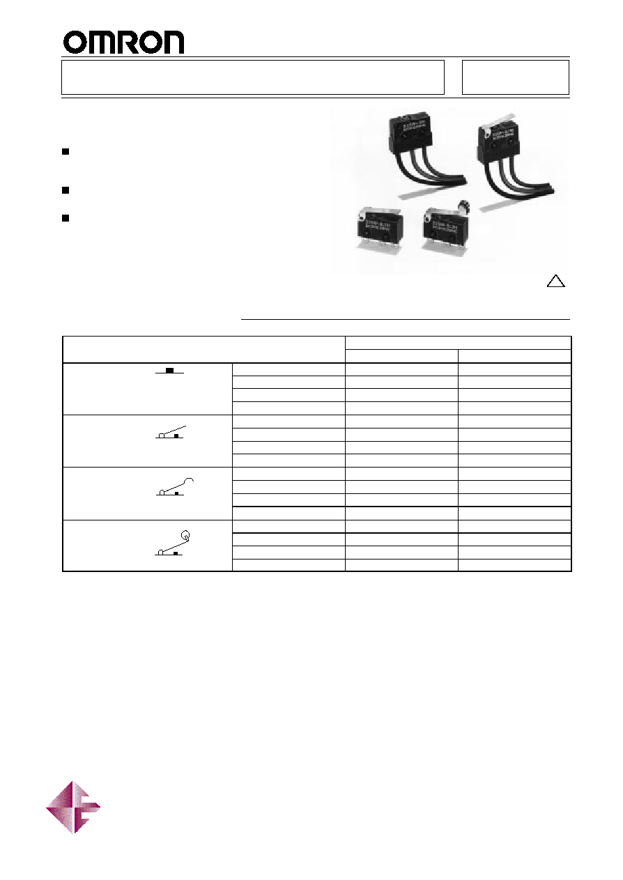
Watertight Miniature Basic Switch
D2SW
A High-quality Watertight Miniature
Basic Switch Conforms to IP67
Monoblock construction assures high sealing
capability and is ideal for dusty places or where
water is sprayed.
A wide operating temperature range of ≠40
∞
C to
85
∞
C is ideal for any operating environment.
Ideal for the automobile, agricultural machinery,
automatic vending machine, refrigerator, ice-
manufacturing, bath equipment, hot-water supply,
air conditioner, and factory machine industries,
which require highly environment-resistive capabil-
ities.
RC
D E
V
Ordering Information
Model
Actuator
3 A
0.1A
Pin plunger
Solder terminals
D2SW-3H
D2SW-01H (see note 2)
p u ge
Tab terminals (#110)
D2SW-3T
D2SW-01T
PCB terminals
D2SW-3D
D2SW-01D
With lead wires
D2SW-3M (see note 3)
D2SW-01M (see note 3)
Hinge lever
Solder terminals
D2SW-3L1H
D2SW-01L1H (see note 2)
ge e e
Tab terminals (#110)
D2SW-3L1T
D2SW-01L1T
PCB terminals
D2SW-3L1D
D2SW-01L1D
With lead wires
D2SW-3L1M (see note 3)
D2SW-01L1M (see note 3)
Simulated hinge lever
Solder terminals
D2SW-3L3H
D2SW-01L3H (see note 2)
S
u a ed
ge e e
Tab terminals (#110)
D2SW-3L3T
D2SW-01L3T
PCB terminals
D2SW-3L3D
D2SW-01L3D
With lead wires
D2SW-3L3M (see note 3)
D2SW-01L3M (see note 3)
Hinge roller lever
Solder terminals
D2SW-3L2H
D2SW-01L2H (see note 2)
ge o e
e e
Tab terminals (#110)
D2SW-3L2T
D2SW-01L2T
PCB terminals
D2SW-3L2D
D2SW-01L2D
With lead wires
D2SW-3L2M (see note 3)
D2SW-01L2M (see note 3)
Note:
1. The standard lengths of the lead wires (AV0.5f) of models incorporating them are 30 cm.
2. EN61058-1 (IEC1058-1) approved by VDE.
3. UL/CSA approved lead-wired models use UL/CSA approved lead wire. Model name changes from D2SW-
j
M to D2SW-
j
MS.
Distributed by: Diamond Electronics Ltd
Tel: +44(0)1477 500450 Fax: +44(0)1477 500656 Mail: sales@diamondelec.co.uk
Web: www.diamondelec.co.uk
D2SW
D2SW
128
Specifications
Ratings
Non-inductive load
Inductive laod
Resistive load
Lamp load
Inductive load
Motor load
Model
Rated voltage
NC
NO
NC
NO
NC
NO
NC
NO
D2SW-3
125 VAC
3 A
1 A
0.5 A
1 A
0.5 A
1 A
0.5 A
250 VAC
2 A
0.5 A
0.3 A
0.5 A
0.3 A
0.5 A
0.3 A
30 VDC
3 A
1 A
1 A
1 A
D2SW-01
125 VAC
0.1 A
---
---
---
30 VDC
0.1 A
---
---
---
Note:
1. The above current ratings are the values of the steady-state current.
2. Inductive load has a power factor of 0.7 min. (AC) and a time constant of 7 ms max. (DC).
3. Lamp load has an inrush current of 10 times the steady-state current.
4. Motor load has an inrush current of 6 times the steady-state current.
Approved Standards
UL (File No. E32667)/CSA (File No. LR21642)
D2SW-3
j
:
3 A at 125 VAC, 2 A at 250 VAC
D2SW-01
j
:
0.1 A at 125 VAC, 0.1 A at 30 VDC
VDE (Licence No. 85002)/EN61058-1 (IEC1058-1) Approved
D2SW-01
j
H:
0.1 A at 125 VAC
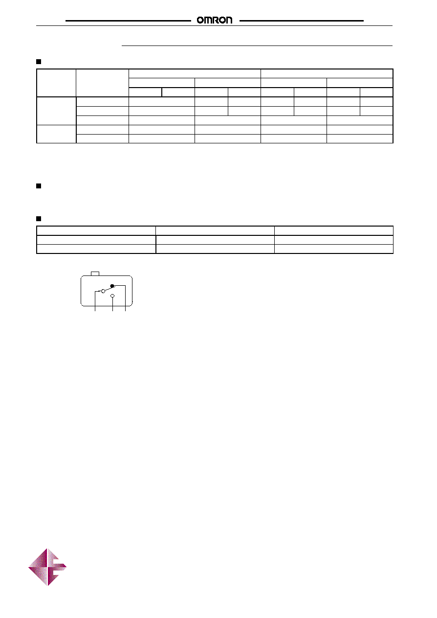
Contact
Item
D2SW-3
D2SW-01
Specification
Rivet
Crossbar
Material
Silver
Gold alloy
Contact Form
NC
(Red*)
NO
(Blue*)
COM
(Black*)
*Indicates the color of the lead wire.
Distributed by: Diamond Electronics Ltd
Tel: +44(0)1477 500450 Fax: +44(0)1477 500656 Mail: sales@diamondelec.co.uk
Web: www.diamondelec.co.uk
D2SW
D2SW
129
Characteristics
Item
D2SW-3
D2SW-01
Operating speed
(see note)
0.1 mm to 1 m/s (at pin plunger)
Operating frequency
Mechanical: 300 operations/min
Electrical:
60 operations/min
Insulation resistance
100 M
min. (at 500 VDC)
Contact resistance
50 m
max. (initial value) for lead wire models
70 m
max. (initial value) for lead wire models
Dielectric strength
1,000 VAC, 50/60 Hz for 1 min between contacts of
the same polarity
1,500 VAC, 50/60 Hz for 1 min between
current-carrying metal parts and ground, and between
each terminal and non-current-carrying metal part
600 VAC, 50/60 Hz for 1 min between contacts
of the same polarity
1,500 VAC, 50/60 Hz for 1 min between
current-carrying metal parts and ground, and
between each terminal and non-current-carrying
metal part
Inrush current
NO: 10 A
NC: 20 A
NO: 1 A
NC: 1 A
Vibration resistance
Malfunction: 10 to 55 Hz, 1.5-mm double amplitude
Shock resistance
Malfunction: 300 m/s
2
(approx. 30G)
Life expectancy
Mechanical: 5,000,000 operations min. (OT value)
Electrical:
200,000 operations min. (3 A at
125 VAC), 100,000 operations min. (2 A at 250 VAC)
Mechanical: 5,000,000 operations min.
(OT value)
Electrical:
200,000 operations min.
Ambient temperature
Operating: ≠40
∞
C to 85
∞
C (with no icing)
Ambient humidity
Operating: 95% max.
Enclosure ratings
IP67 for lead wire models
IP50 for terminal models
Weight
Terminal model: 2 g, Lead wire model: 10 g
Note:
The operating speed value shown is for pin plunger models. For hinge lever models, this speed is for the plunger parts.
VDE-approved Characteristics (EN61058-1)
Degree of protection against
electric shock
Class 1
Ambient temperature
0
∞
C to 85
∞
C
Operating cycles
50,000
Proof tracking index (PTI)
175 V
Switch category (IEC335-1)
A
Operating Characteristics
Type
Pin plunger
Hinge lever
Simulated hinge lever
Hinge roller lever
D2SW-3
j
D2SW-01
j
D2SW-3L1
j
D2SW-01L1
j
D2SW-3L3
j
D2SW-01L3
j
D2SW-3L2
j
D2SW-01L2
j
OF max.
1.77 N (180 gf)
0.59 N (60 gf)
0.59 N (60 gf)
0.59 N (60 gf)
RF min.
0.29 N (30 gf)
0.06 N (6 gf)
0.06 N (6 gf)
0.06 N (6 gf)
PT max.
0.6 mm
---
---
---
OT min.
0.5 mm
1.0 mm
1.0 mm
1.0 mm
MD max.
0.1 mm
0.8 mm
0.8 mm
0.8 mm
FP max.
---
13.6 mm
15.5 mm
19.3 mm
OP
8.4
±
0.3 mm
8.8
±
0.8 mm
10.7
±
0.8 mm
14.5
±
0.8 mm
Distributed by: Diamond Electronics Ltd
Tel: +44(0)1477 500450 Fax: +44(0)1477 500656 Mail: sales@diamondelec.co.uk
Web: www.diamondelec.co.uk
D2SW
D2SW
130
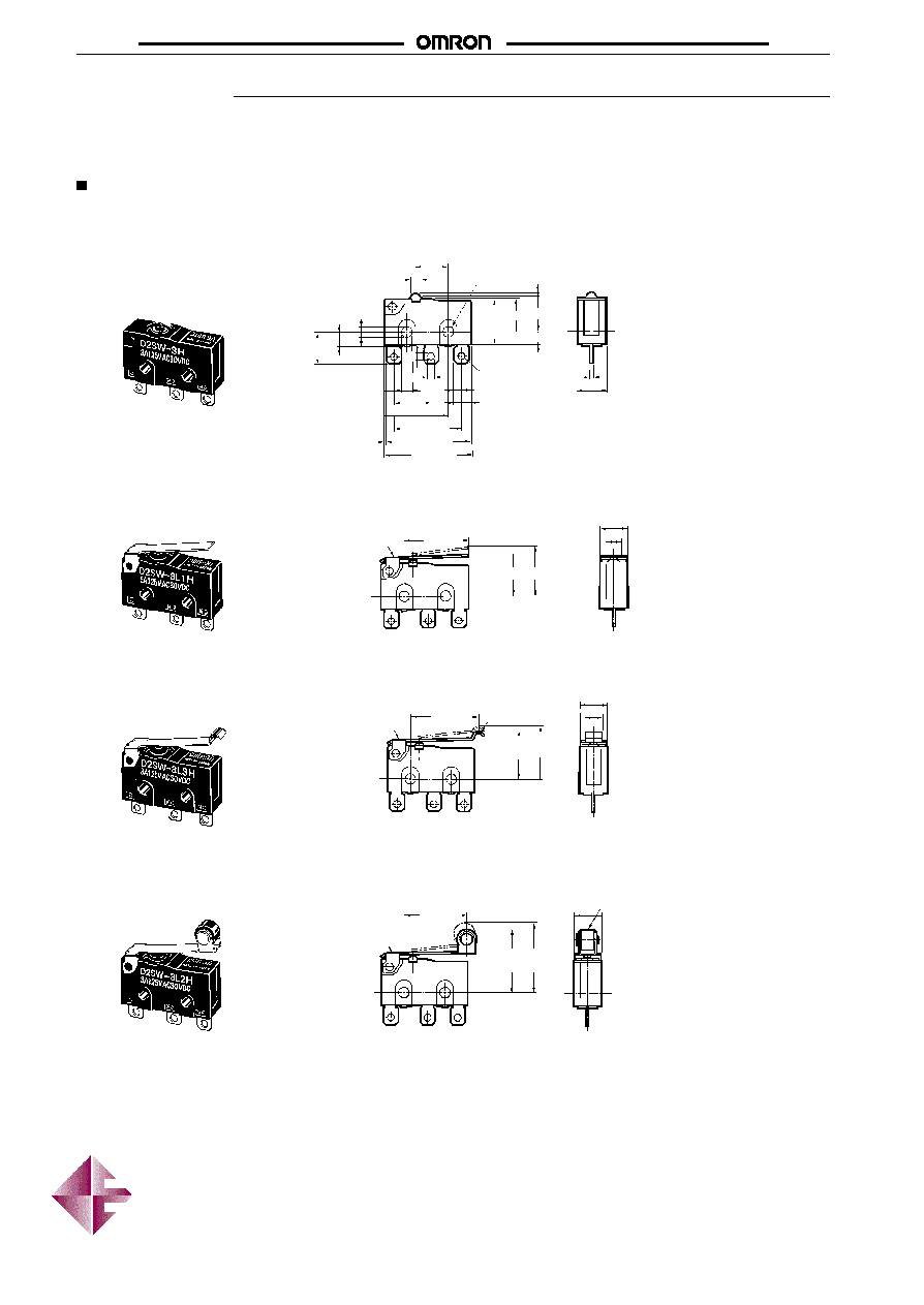
Dimensions
Note:
1. All units are in millimeters unless otherwise indicated.
2. Every actual model number includes the code instead of
j
for the kind of terminals incorporated by the model.
3. Unless otherwise specified, a tolerance of
±
0.4 mm applies to all dimensions.
Terminal Model
Note:
The following illustrations and dimensions are for models with soldered terminals. Refer to
Terminals for models with tab (#110) and
PCB terminals. The dimensions not described are the same as those of models with pin plungers.
Pin Plunger
D2SW-3
j
D2SW-01
j
Hinge Lever
D2SW-3L1
j
D2SW-01L1
j
Simulated Hinge Lever
D2SW-3L3
j
D2SW-01L3
j
0.5
6.4
±
0.2
PT
OP
2.9
7.7
10.1
R0.8
1.6
3.2
1.8 dia.
7.5
±
0.1
7.3
3.3
±
0.1
1.8
1.6
2.5 dia.
±
0.07
5.15
0.55
19.8
±
0.2
15.5
±
0.2
18.7
±
0.2
9.5
±
0.1
8.5
±
0.2
14.5
OP
t = 0.3
Stainless
steel lever
5.9
3.6
15.8
OP
FP
5.9
3.6
t = 0.3 Stainless
steel lever
2.35
+0.1
≠0.05
2.35
+0.1
≠0.05
dia.
holes
FP
R1.3
Hinge Roller Lever
D2SW-3L2
j
D2SW-01L2
j
t = 0.3 Stainless
steel lever
14.5
OP
FP
5.9
4.8 dia. x 3.2
Polyacetal roller
Distributed by: Diamond Electronics Ltd
Tel: +44(0)1477 500450 Fax: +44(0)1477 500656 Mail: sales@diamondelec.co.uk
Web: www.diamondelec.co.uk
D2SW
D2SW
131
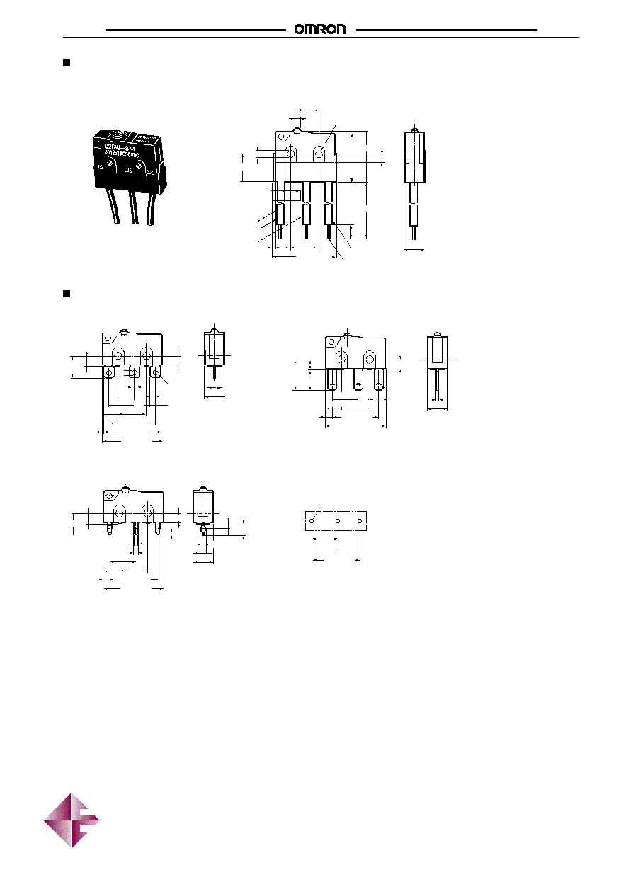
Lead Wire Model
Note:
The following illustration and dimensions are for models with pin plungers. The dimensions and operating characteristics of the actua-
tors of models incorporating them are the same as those of the actuators of models with both actuators and terminals.
Common terminal (black)
Vinyl insulator
Normally open terminal (blue)
Stranded annealed copper wires
Normally
closed terminal
(red)
2.9
9.2
7.5
±
0.1
1.8 dia.
16.4 16.9
300
±
10
(5)
6.4
±
0.2
21.2
5.15
9.5
±
0.1
2.35
+0.1
≠0.05
2.35
+0.1
≠0.05
dia. holes
2.5 dia.
±
0.07
0.7
Kind of Terminals
3.3
±
0.1
2.9
10.1
6.6
Three,
2.8
8.7
±
0.2
5.15
9.5
±
0.1
15.5
±
0.2
19.8
±
0.2
2.15
0.5
6.4
±
0.2
Three,
1.2 dia.
holes
7.3
3.3
±
0.1
1.8
1.6
2.9
R0.8
1.6
3.2
6.4
±
0.2
0.5
19.8
±
0.2
8.5
±
0.2
5.15
9.5
±
0.1
15.5
±
0.2
18.7
±
0.2
7.2
3.3
±
0.1
0.8
1.2
8.8
±
0.2
5.15
1.85
9.5
±
0.1
Three, 1.35 dia. to 1.5 holes
PCB thickness
t = 1.6 mm
1.3
6.4
±
0.2
0.5
1.8
±
0.1
2.9
0.7
3.9
Solder Terminals
Tab Terminals (#110)
PCB Terminals
PCB Mounting
8.8
+0.15
≠0.05
16.1
±
0.1
0.55
19.8
±
0.2
16.1
±
0.2
Distributed by: Diamond Electronics Ltd
Tel: +44(0)1477 500450 Fax: +44(0)1477 500656 Mail: sales@diamondelec.co.uk
Web: www.diamondelec.co.uk