 | –≠–ª–µ–∫—Ç—Ä–æ–Ω–Ω—ã–π –∫–æ–º–ø–æ–Ω–µ–Ω—Ç: D4C-1632 | –°–∫–∞—á–∞—Ç—å:  PDF PDF  ZIP ZIP |
Document Outline
- Front Page
- Ordering Information
- Construction
- Specifications
- Engineering Data
- Operation
- Dimensions
- Installation
- Contacting Omron
D4C
D4C
2
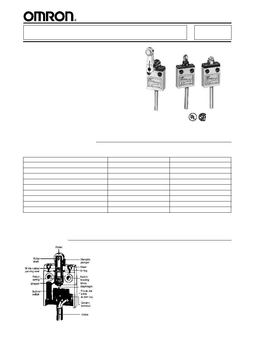
Sealed, Compact, Slim
Prewired Limit Switch
s
Rugged diecast housing
s
Meets UL types 3, 4 and 13
s
Triple-sealed construction
s
Designed for easy gang mounting
s
Rated load of 5 amps, 250 VAC
s
Prewired with 3 m (9.8 ft) or
5 m (16.4 ft) of cable
Ordering Information
Slim Enclosed Limit Switches
D4C
s
LIMIT SWITCHES
Actuator
3 m (9.8 ft) cable
5 m (16.4 ft) cable (See Note.)
Pin plunger
D4C-1601
D4C-1701
Sealed plunger
D4C-1631
D4C-1731
Roller plunger
D4C-1602
D4C-1702
Sealed roller plunger
D4C-1632
D4C-1732
Cross roller plunger
D4C-1603
D4C-1703
Sealed cross roller plunger
D4C-1633
D4C-1733
Bevel plunger
D4C-1610
D4C-1710
Coil spring
D4C-1650
D4C-1750
Roller lever
D4C-1620
D4C-1720
Note:
5 m cable types are available on special order only.
Construction
D4C
D4C
3
Specifications
s
RATINGS
s
APPROVED RATINGS
UL/CSA Approved Ratings
Model
Rated voltage
Non-inductive load
Inductive load
Inrush current
Resistive load
Lamp load
Inductive load
Motor load
NC
NO
NC
NO
NC
NO
NC
NO
NC
NO
D4C-1
125 VAC
5 A
5 A
1.5 A
0.7 A
3 A
3 A
2.5 A
1.3 A
20 A
10 A
250 VAC
5 A
5 A
1 A
0.5 A
2 A
2 A
1.5 A
0.8 A
8 VDC
5 A
5 A
2 A
2 A
5 A
4 A
3 A
3 A
14 VDC
5 A
5 A
2 A
2 A
4 A
4 A
3 A
3 A
30 VDC
4 A
4 A
2 A
2 A
3 A
3 A
3 A
3 A
125 VDC
0.4 A
0.4 A
0.05 A
0.05 A
0.4 A
0.4 A
0.05 A
0.05 A
250 VDC
0.2 A
0.2 A
0.03 A
0.03 A
0.2 A
0.2 A
0.03 A
0.03 A
max
max
Note:
1. Inductive loads have a power factor of 0.4 min. (AC) and a time constant of 7 ms max. (DC).
2. Lamp loads have an inrush current of 10 times the steady-state current.
3. Motor loads have an inrush current of 6 times the steady-state current.
Approval
Standard
File no.
UL
UL508
E76675
CSA
CSA C22.2 No. 14
LR45746
B300 (D4C-16
, -17
)
NEMA B300 (D4C-16
, -17
)
Rated voltage
Current
Voltamperes
Make
Break
Make
Break
120 VAC
30 A
3 A
3,600 VA
360 VA
250 VAC
15 A
1.5 A
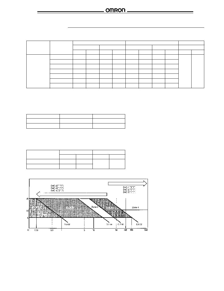
Applicable Load Range
D4C
D4C
4
Operating speed
0.1 mm to 0.5 m/s (D4C-
20:1 mm to 1 m/s)
Operating frequency
Mechanical
120 operations/min
Electrical
30 operations/min
Insulation resistance
100 M min. (at 500 VDC)
Rated insulation voltage (U
i
)
300 V (IEC947-5-1)
Rated impulse withstand voltage (U
imp
)
2.5 kV (IEC947-5-1)
Switching overvoltage
1,000 VAC, 300 VDC max. (IEC947-5-1)
Short-circuit protective device
10 A fuse (type gG) (IEC269)
Conditional short-circuit current
100 A (IEC947-5-1)
Contact resistance
300 m (initial value with 3 m VCTF cable)
400 m (initial value with 5 m VCTF cable)
Dielectic strength
1,000 VAC, 50/60 Hz for 1 min between non-continuous terminals
1,500 VAC, 50/60 Hz for 1 min between current-carrying metal part and ground, and
between each terminal and non-current-carrying metal part
Vibration resistance
Malfunction
10 to 55 Hz, 1.5 mm double amplitude
Shock resistance
Destruction
Approx. 1,000 m/s
2
(approx. 100 G)
Malfunction
Approx. 500 m/s
2
(approx. 50 G)
Ambient temperature
Operating
-10
∞
C to 70
∞
C (14
∞
F to 158
∞
F)
Ambient humidity
Operating
95% max
Operating environmental pollution level
Pollution degree 3 (IEC947-5-1)
Life expectancy
Mechanical
10,000,000 operations min. (at 1.5 to 2 mm OT)
Electrical
See:
Engineering Data
Enclosure ratings
UL
Types 3, 4 and 13
NEMA
Types 1, 3, 3R, 4, 5, 6, 12 and 13
IEC
IP67
Weight
With 3 m VCTF cable: 360 g
With 5 m VCTF cable: 540 g
s
CHARACTERISTICS
s
OPERATING CHARACTERISTICS
Part number
Description
OF
RF
OT
PT
MD
OP
D4C-
01
Pin plunger
1.2 kg
450 g
3 mm
1.8 mm
0.2 mm
15.7
±
1 mm
(42.32 oz)
(15.87 oz)
(0.118 in)
(0.07 in)
(0.008 in)
(0.62
±
0.04 in)
D4C-
31
Sealed plunger
1.8 kg
450 g
3 mm
1.8 mm
0.2 mm
24.9
±
1 mm
(63.49 oz)
(15.87 oz)
(0.118 in)
(0.07 in)
(0.008 in)
(0.99
±
0.04 in)
D4C-
02
Roller plunger
1.2 kg
450 g
3 mm
1.8 mm
0.2 mm
28.5
±
1 mm
(42.32 oz)
(15.87 oz)
(0.118 in)
(0.07 in)
(0.008 in)
(1.12
±
0.04 in)
D4C-
32
Sealed roller plunger
1.8 kg
450 g
3 mm
1.8 mm
0.2 mm
34.3
±
1 mm
(63.49 oz)
(15.87 oz)
(0.118 in)
(0.07 in)
(0.008 in)
(1.35
±
0.04 in)
D4C-
03
Cross roller plunger
1.2 kg
450 g
3 mm
1.8 mm
0.2 mm
28.5
±
1 mm
(42.32 oz)
(15.87 oz)
(0.118 in)
(0.07 in)
(0.008 in)
(1.12
±
0.04 in)
D4C-
33
Sealed cross roller
1.8 kg
450 g
3 mm
1.8 mm
0.2 mm
34.3
±
1 mm
plunger
(63.49 oz)
(15.87 oz)
(0.118 in)
(0.07 in)
(0.008 in)
(1.35
±
0.04 in)
D4C-
10
Bevel plunger
1.2 kg
450 g
3 mm
1.8 mm
0.2 mm
28.5
±
1 mm
(42.32 oz)
(15.87 oz)
(0.118 in)
(0.07 in)
(0.008 in)
(1.12
±
0.04 in)
D4C-
50
Coil spring
150 g
--
--
15
∞
--
--
(5.29 oz)
D4C-
20
Roller lever
580 g
150 g
40
∞
25
∞
3
∞
--
(20.46 oz)
(5.29 oz)
Legend: OF = Operating Force (max.); RF = Reset Force (min.); OT = Overtravel (min.); PT = Pretravel
MD = Movement Differential (max.); OP = Operating Position
D4C
D4C
5
s
CONTACT FORM
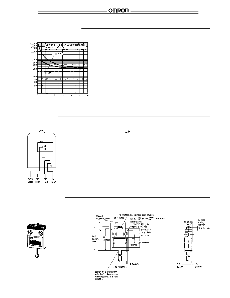
Operation
Engineering Data
s
ELECTRICAL LIFE EXPECTANCY
Switching current (mA)
Life expectancy (x 10
3
operations)
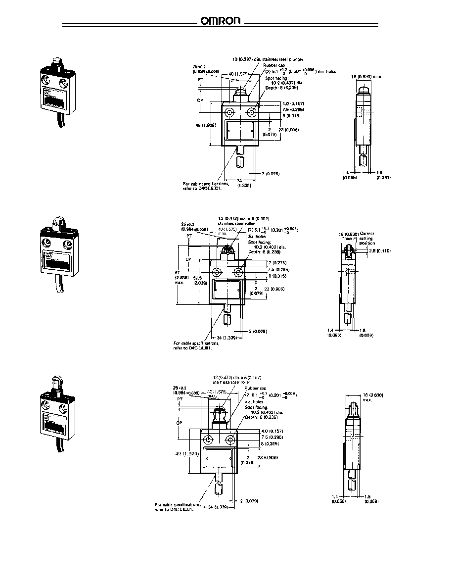
Dimensions
Unit: mm (inch)
s
LIMIT SWITCHES
D4C-
01 Pin Plunger Switch
s
CONTACT RATINGS
NEMA B300
s
CONTACT RESISTANCE
30 m
max, initial value with 3 m (9.84 ft) cable
s
ELECTRICAL APPROVALS
UL Recognized, File No. E76675
CSA Certified, File No. LR45746
(COM) 1
2 (NC)
4 (NO)
EN60947-1
D4C
D4C
6
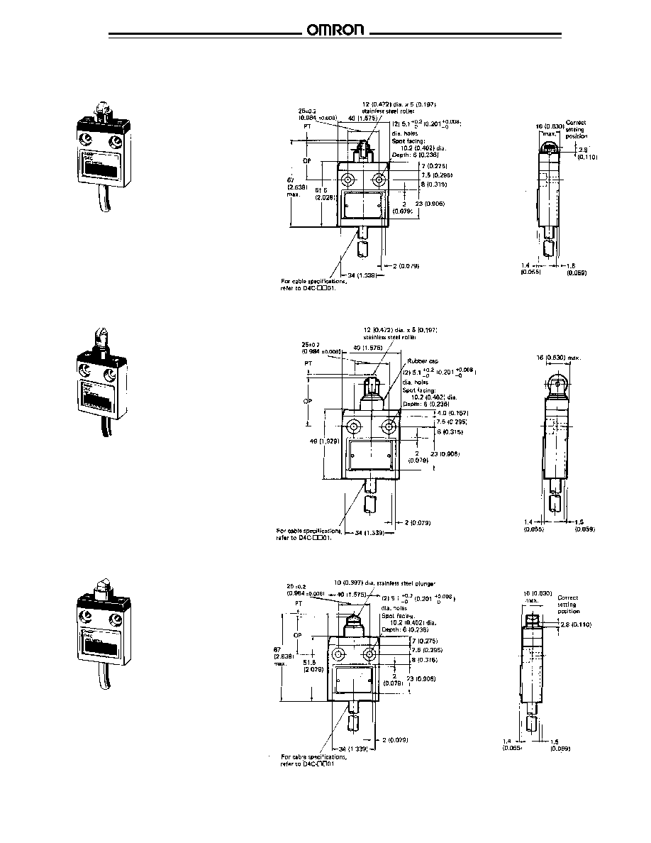
D4C-
31 Sealed Plunger Switch
D4C-
02 Roller Plunger Switch
D4C-
32 Sealed Roller Plunger Switch
D4C
D4C
7
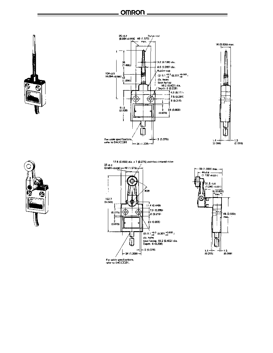
Unit: mm (inch)
D4C-
03 Cross Roller Plunger Switch
D4C-
33 Sealed Cross Roller Plunger Switch
D4C-
10 Bevel Plunger Switch
D4C
D4C
8
D4C-
50 Coil Spring Switch
D4C-
20 Roller Lever Switch
D4C
D4C
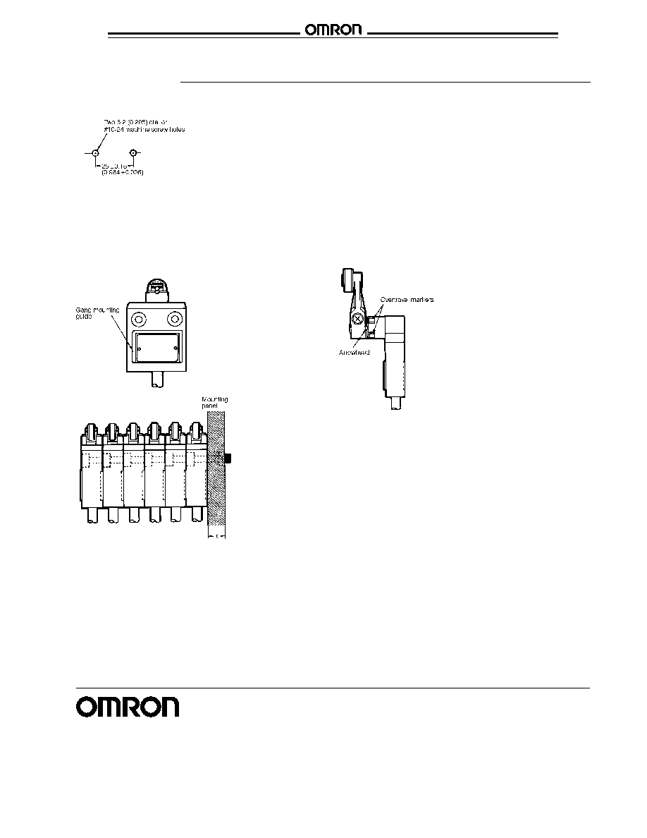
s
GANG MOUNTING SWITCHES
A maximum of 6 switch units may be gang mounted. See the
figures for proper orientation of switches.
s
OVERTRAVEL MARKERS
To allow the roller lever type actuator to travel properly, set the
roller lever according to the dog or cam stroke so that the
arrowhead of the lever is positioned between the two overtravel
markers as shown.
s
PROPER CAM SHAPE
Operation method, shapes of cam and dog, operating frequency,
and overtravel have a significant effect on the service life and
precision of a limit switch. For this reason, the cam angle should
be 30
∞
max. The surface roughness of the cam should be 6.3
microns min., and the hardness of the cam must be about Hv450
(Brinell #425).
s
CABLE TIE POSITIONING
The bottom of the enclosed switch at the cable outlet is resin-
molded. Secure the cable at a point 5 cm (1.97 in) from the
switch bottom to prevent exertion of undue force on the cable.
Installation
s
MOUNTING HOLES
Secure the switch to the mounting panel with
two #10-24 machine screws and washers and
tighten them from 3.6 ft∑lb to 4.3 ft∑lb torque.
OMRON ELECTRONICS LLC
OMRON CANADA, INC.
One East Commerce Drive
885 Milner Avenue
Schaumburg, IL 60173
Scarborough, Ontario M1B 5V8
1-800-55-OMRON
416-286-6465
Cat. No. CEDSAX4
11/01
Specifications subject to change without notice.
Printed in the U.S.A.
OMRON ON-LINE
Global - http://www.omron.com
USA - http://www.omron.com/oei
Canada - http://www.omron.com/oci