1
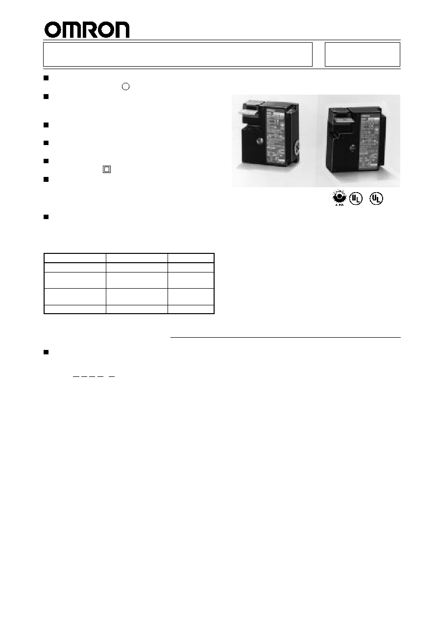
Compact Guard-locking Interlock Safety Door Switch
D4DL
Polymer housing, IP65, and slow-action contacts
with positive opening
.
2 versions
∑
Mechanical lock/Solenoid release
∑
Solenoid lock/Mechanical release
Rotatable operating head provides four possible
key entry slots.
Incorporates an indicator that shows operation
status at a glance.
Double-insulation structure requires no grounding
terminals. (with
mark)
Three types of Operation Key are available:
∑
Horizontal mounting
∑
Vertical mounting
∑
Angle-adjustable vertical mounting
Safety Standards
Conformity:
Machinery Directive, Low-voltage Directive, EN1088, SUVA
Approval:
Agency
Standard
File No.
TÐV Rheinland
EN60947-5-1
J9650736
BIA
EN60947-5-1,
GS-ET-19
9610568
UL (see note)
UL508, CSA C22.2
No.14
E76675
SUVA
SUVA
Pending
Note:
Approval for CSA C22.2 No. 14 is authorized by
c
u
mark.
E
c
Ordering Information
Model Number Legend
Switches
D4DL-
jjjj
-
j
1
2
3
4
5
1.
Conduit Size (2-conduit)
1:
Pg13.5
2:
G
1
/
2
2.
Built-in Switch (with Safety Switch and Lock Monitor
Switch Contacts)
C:
1NC/1NO slow-action contacts plus 1NC slow-action
contact
D:
2NC slow-action contacts plus 1NC slow-action contact
3.
Head Mounting Direction
F:
Front
4.
Door Lock and Release
A:
Mechanical lock / 24-VDC solenoid release (see note)
B:
Mechanical lock / 110-VAC solenoid release
C:
Mechanical lock / 230-VAC solenoid release
G:
24-VDC solenoid lock / mechanical release (see note)
H:
110-VAC solenoid lock / mechanical release
J:
230-VAC solenoid lock / mechanical release
5.
Indicator
B:
10 to 115 VAC/VDC (with orange LED indicator)
E:
100 to 250 VAC (with orange neon lamp indicator)
D4DL
D4DL
2
Operation Keys
D4DS-K
j
1
1.
Key Type
1:
Horizontal mounting
2:
Vertical mounting
3:
Horizontal-adjustable vertical mounting
5:
Vertical/Horizontal-adjustable vertical mounting
Switches
Solenoid voltage/indicator
Lock and release
types
Contact configuration
(Slow-action)
Approved force-separation
NC contact
Connector size
Model
Solenoid: 24 VDC
O
LED 10 t 115 VDC/VAC
Mechanical lock
S l
id
l
1NC/1NO+1NC
PG13.5
D4DL-1CFA-B
So e o d
C
Orange LED: 10 to 115 VDC/VAC
ec a ca oc
Solenoid release
C/
O
C
G1/2
D4DL-2CFA-B
2NC+1NC
PG13.5
D4DL-1DFA-B
C
C
G1/2
D4DL-2DFA-B
Solenoid lock
M
h
i
l
l
1NC/1NO+1NC
PG13.5
D4DL-1CFG-B
So e o d oc
Mechanical release
C/
O
C
G1/2
D4DL-2CFG-B
2NC+1NC
PG13.5
D4DL-1DFG-B
C
C
G1/2
D4DL-2DFG-B
Solenoid: 110 VAC
O
LED 10 t 115 VDC/VAC
Mechanical lock
S l
id
l
1NC/1NO+1NC
PG13.5
D4DL-1CFB-B
So e o d
0
C
Orange LED: 10 to 115 VDC/VAC
ec a ca oc
Solenoid release
C/
O
C
G1/2
D4DL-2CFB-B
2NC+1NC
PG13.5
D4DL-1DFB-B
C
C
G1/2
D4DL-2DFB-B
Solenoid lock
M
h
i
l
l
1NC/1NO+1NC
PG13.5
D4DL-1CFH-B
So e o d oc
Mechanical release
C/
O
C
G1/2
D4DL-2CFH-B
2NC+1NC
PG13.5
D4DL-1DFH-B
C
C
G1/2
D4DL-2DFH-B
Solenoid: 230 VDC
O
l
100 t 250 VAC
Mechanical lock
S l
id
l
1NC/1NO+1NC
PG13.5
D4DL-1CFC-E
So e o d
30
C
Orange neon lamp: 100 to 250 VAC
ec a ca oc
Solenoid release
C/
O
C
G1/2
D4DL-2CFC-E
2NC+1NC
PG13.5
D4DL-1DFC-E
C
C
G1/2
D4DL-2DFC-E
Solenoid lock
M
h
i
l
l
1NC/1NO+1NC
PG13.5
D4DL-1CFJ-E
So e o d oc
Mechanical release
C/
O
C
G1/2
D4DL-2CFJ-E
2NC+1NC
PG13.5
D4DL-1DFJ-E
C
C
G1/2
D4DL-2DFJ-E
Note:
Models marked with "
" are recommended
Operation Keys (Order Separately)
Type
Model
Horizontal mounting
D4DS-K1
Vertical mounting
D4DS-K2
Horizontal-adjustable
vertical mounting
D4DS-K3
Vertical/Horizontal
adjustable vertical
mounting
D4DS-K5
D4DL
D4DL
3
Specifications
Approved Standard Ratings
TÐV (EN60947-5-1)
Item
LED type
Neon lamp
type
Utilization category
AC-15
AC-15
Rated operating current (I
e
)
6 A
3 A
Rated operating voltage (U
e
)
115 V
250 V
Note:
Use a 10-A fuse type gI or gG as a short-circuit protection device that conforms to IEC269.
UL/CSA (UL508, CSA C22.2 No. 14)
A300
Rated voltage
Carry current
Current (A)
Voltage
a ed o age
Ca y cu e
Make
Break
Make
Break
120 VAC
10A
60
6
7,200
720
240 VAC
0
30
3
, 00
0
Characteristics
Degree of protection (see note 2)
IP65 (EN60947-5-1)
Life expectancy (see note 3)
Mechanical:1,000,000 times min.
Electrical:
500,000 times min.
Operating speed
0.05 to 0.5 m/s
Operating frequency
30 operations/minute max.
Rated frequency
50/60 Hz
Positive opening force (see note 4)
58.84 N {6 kgf} min. (EN60947-5-1)
Positive opening travel (see note 4)
10 mm min. (EN60947-5-1)
Holding force
500 N {51 kgf} min. (GS-ET-19)
Insulation resistance
100 M
min. (at 500 VDC)
Rated insulation voltage (U
i
)
300 V (EN60947-5-1)
Conventional enclosed thermal current
(I
the
)
10 A (EN60947-5-1)
Rated impulse voltage (U
imp
)
Between terminals of same or different polarity, each terminal and ground, and each
terminal and non-current-carrying metal part: 4 kV
Between the solenoid and non-current-carrying metal part: 0.8 kV for 24 VDC solenoid,
2.5 kV for 110 VAC solenoid, and 4 kV for 230 VAC solenoid (EN60947-5-1)
Conditional short-circuit current
100 A (EN60947-5-1)
Pollution degree (operating environment)
3 (EN60947-5-1)
Protection against electric shock
Class II (double insulation)
Switching overvoltage
1,500 V max. (EN60947-5-1)
Contact resistance
25 m
max. (initial value)
Vibration resistance
Malfunction:10 to 55 Hz, 0.75-mm single amplitude
Shock resistance
Mechanical:1,000 m/s
2
(100G) min.
Malfunction:300 m/s
2
(30G) min.
Ambient temperature
Operating: ≠10
∞
C to 55
∞
C with no icing
Ambient humidity
Operating: 95% max.
Weight
Approx. 340 g (D4DL-1CFA-B)
Material
Body and actuator flange
Glass-fiber reinforced thermoplast, self-extinguishing
a e a
Actuator
Stainless steel
Note:
1. The above values are initial values.
2. Although the switch box is protected from dust or water penetration, do not use the D4DL in places where foreign material may
penetrate through the key hole on the head, otherwise switch damage or malfunctioning may occur.
3. The above mechanical or electrical life is ensured at an ambient temperature of 5
∞
C to 35
∞
C and an ambient humidity of 40% to 70%.
4. These values must be satisfied to ensure safe operation.
D4DL
D4DL
4
Solenoid Characteristics
Item
24 VDC
110 VAC
230 VAC
Rated operating voltage
24 VDC
+10%
/
≠15%
(100% ED)
110 VAC
±
10% (100% ED)
230 VAC
±
10% (100% ED)
Current consumption
Approx. 200 mA
Approx. 50 mA
Approx. 30 mA
Insulation
Class F (130
∞
C max.)
Class F (130
∞
C max.)
Class F (130
∞
C max.)
Indicator
Item
LED
Neon lamp
Rated voltage
10 to 115 VAC/VDC
100 to 250 VAC
Current leakage
Approx. 1 mA
Approx. 1.9 mA
Color
Orange
Orange
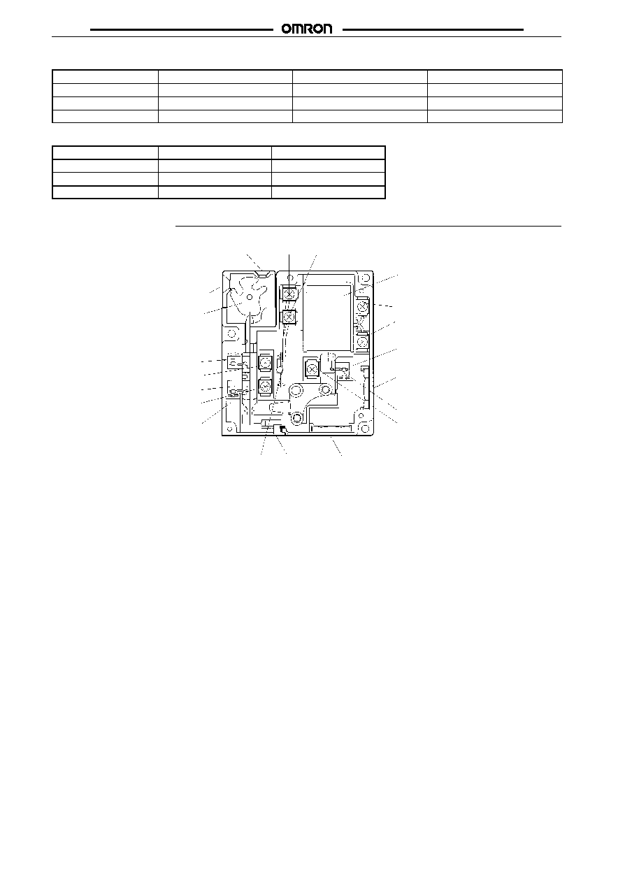
Nomenclature
Operation key hole
Terminal E3
Terminal E4
Operation key hole
Cam
Terminal 11
Terminal 12
Terminal 23
Terminal 24
Main switch
Indicator
Release key
Conduit opening
Solenoid
Lock monitor switch
Terminal E1 ( )
Terminal E2 ( )
Conduit opening
Terminal 32
Terminal 31
+
~
≠
~
D4DL
D4DL
5
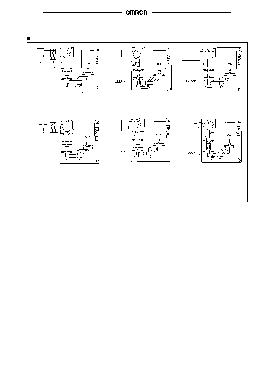
Operation
Operation Principles
Mechanical lock model
Guard
Inside equipment
Lock spring
11
23
24
12
31
32
∑
Door closed
∑
Access to machine is not allowed.
∑
Lock spring locks the door.
∑
Power to solenoid
∑
Door can be opened.
Solenoid lock model
Lock releasing spring
11
23
24
12
31
32
∑
Door opened
∑
Access to machine is allowed.
∑
Solenoid: OFF
∑
Lock releasing spring releases
the door lock.
∑
Solenoid: OFF
∑
Door can be opened.
∑
Solenoid: ON
∑
Door locked
∑
Access to the machine is not
allowed.