R
2
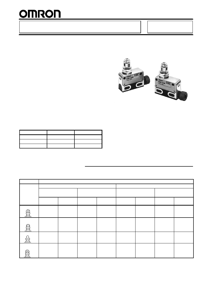
Miniature Enclosed Limit Switch
D4E-j
j
j
j
N
Slim and Compact with a Long Life
H
Cover protects the built-in switch from
dust and oil
H
Durable plunger sealing cap ensures
long life
H
Connector type, screw-terminal type
and pre-wired type are available
H
Micro load type uses gold cladded
contacts
H
Designed for gang mounting
H
Molded terminal types and
operation-indicator types are available
H
Approved standards
Agency
Standards
File No.
UL
UL508
E76675
CSA
CSA C22.2 No. 14
LR45746
TÐV Rheinland
EN60947-5-1
R9551015
Ordering Information
J
LIMIT SWITCHES
Item
Part number
Actuator
Connector type
Screw terminal type
5A type
0.1A type
5A type
0.1A type
AC
connector
DC
connector
AC
connector
DC
connector
Without
cable
With cable
Without
cable
With cable
Roller plunger
D4E-1A00N
D4E-1A10N
D4E-2A00N
D4E-2A10N
D4E-1A20N
D4E-1A21N
D4E-2A20N
D4E-2A21N
Cross-roller
plunger
D4E-1B00N
D4E-1B10N
D4E-2B00N
D4E-2B10N
D4E-1B20N
D4E-1B21N
D4E-2B20N
D4E-2B21N
Plunger
D4E-1C00N
D4E-1C10N
D4E-2C00N
D4E-2C10N
D4E-1C20N
D4E-1C21N
D4E-2C20N
D4E-2C21N
Sealed roller
plunger
D4E-1D00N
D4E-1D10N
D4E-2D00N
D4E-2D10N
D4E-1D20N
D4E-1D21N
D4E-2D20N
D4E-2D21N
D4E-j
j
j
j
N
D4E-j
j
j
j
N
3
Ordering Information Table
-- continued from previous page
Item
Part number
Actuator
Connector type
Screw terminal type
5A type
0.1A type
5A type
0.1A type
AC
connector
DC
connector
AC
connector
DC
connector
Without
cable
With cable
Without
cable
With cable
Sealed cross-
roller plunger
D4E-1E00N
D4E-1E10N
D4E-2E00N
D4E-2E10N
D4E-1E20N
D4E-1E21N
D4E-2E20N
D4E-2E21N
Sealed plunger
D4E-1F00N
D4E-1F10N
D4E-2F00N
D4E-2F10N
D4E-1F20N
D4E-1F21N
D4E-2F20N
D4E-2F21N
Roller lever
D4E-1G00N
D4E-1G10N
D4E-2G00N
D4E-2G10N
D4E-1G20N
D4E-1G21N
D4E-2G20N
D4E-2G21N
One-way action
roller lever
D4E-1H00N
D4E-1H10N
D4E-2H00N
D4E-2H10N
D4E-1H20N
D4E-1H21N
D4E-2H20N
D4E-2H21N
Note: For Customized Models, refer to Molded Terminal Models or Operation Indicator Models at the end of this data sheet.
J
MODEL NUMBER LEGEND
D4E -
N
1 2
3
1. Rated Current
1: 5 A at 125 VAC
(1 A at 125 VAC/30 VDC for
model with a connector)
2: 0.1 A at 125 VAC
(0.1 A at 125 VAC/30 VDC for
model with a connector)
2. Actuator
A: Roller plunger
B: Cross-roller plunger
C: Plunger
D: Sealed roller plunger
E: Sealed cross-roller plunger
F: Sealed plunger
G: Roller lever
H: One-way action roller lever
3. Terminals
00: AC connector
10: DC connector
20: Screw terminals without a cable
21: Screw terminals with a cable
(S-FLEX VCTF 3 m)
J
ACCESSORIES (ORDER SEPARATELY)
Plug
Model
Current
Type
No. of conductors
Cable length
Applicable models
XS2F-A421-350
AC
Straight
4
2 m
D4E-jj00N
XS2F-A421-450
5 m
XS2F-D421-350
DC
2 m
D4E-jj10N
XS2F-D421-450
5 m

D4E-j
j
j
j
N
D4E-j
j
j
j
N
4
Construction
Movable Plunger
Rubber Cap
Rubber cap provides a tight seal and
ensures long life
Seal Packed
Seal packing withstands a pressure of
27 psi (1.9 kgf/cm
2
)
Terminal Protection Cover
D4E-jN has a wide wiring space of
10 mm
Screw Terminal
Screw terminal incorporates a M3
screw with a toothed washer
Wiring Ease
Plug-in connector
Bearing
Bearing ensures smooth resetting
even if the roller is pressed with ex-
cessive force
The actuator withstands a force of
500 kg (D4E's actuator withstands a
force of 30 kg)
Built-in Switch
Switch cover ensures high insulation
between the terminals and die-cast,
meeting UL/CSA standards
Die-cast Case
Zinc die-cast case is anti-corrosive
and tough
Specifications
J
RATINGS
General Ratings
Rated voltage
General-purpose
Micro load
Non-inductive load
Inductive load
Non-inductive load
Resistive load
Lamp load
Inductive load
Motor load
Resistive load
NC
NO
NC
NO
NC
NO
NC
NO
NC
NO
125 VAC
5 (1) A
1.5 (1) A
3 (1) A
2 (1) A
1 (1) A
0.1 A
250 VAC
5 (1) A
1.5 (1) A
3 (1) A
1 A
0.5 A
---
8 VDC
5 (1) A
---
1.5 (1) A
---
0.1 A
14 VDC
5 (1) A
---
1.5 (1) A
---
0.1 A
30 VDC
5 (1) A
---
1.5 (1) A
---
0.1 A
125 VDC
0.5 A
---
0.05 A
---
---
250 VDC
0.25 A
---
0.03 A
---
---
Note: 1. The above current ratings are for steady-state current and the value in parentheses is for models with a connector.
2. Inductive loads have a power factor of 0.4 min. (AC) and a time constant of 7 ms max. (DC).
3. Lamp loads have an inrush current of 10 times the steady-state current.
4. Motor loads have an inrush current of 6 times the steady-state current.

D4E-j
j
j
j
N
D4E-j
j
j
j
N
6
J
CHARACTERISTICS
Operating speed
0.1 mm to 0.5 m/sec (0.0039 to 19.6 in/s)
Operating frequency
Mechanical
120 operations/min
p
g
q
y
Electrical
30 operations/min
Insulation resistance
100 M min. (at 500 VDC)
Contact resistance
15 m max. (initial value)
Dielectric strength
1,000 VAC, 50/60 Hz for 1 min between terminals of same polarity
1,500 VAC, 50/60 Hz for 1 min between current-carrying metal parts and
ground, and between each terminal and non-current-carrying metal part
Inrush current
NC/NO: 10 A max.
Rated insulation voltage (U
i
)
250 VAC (EN60947-5-1)
Rated impulse withstand voltage (U
imp
)
6 kV (EN60947-5-1)
Operating environment pollution degree
3 (EN60947-5-1)
Short-circuit protective device
Fuse (type gG or gI, IEC269 approved)
Conventional enclosed thermal current
5 A (0.5 A for micro load type) (EN60947-5-1)
Protection against electric shock
Class II (double insulation)
Vibration resistance
Malfunction: 10 to 55 Hz, 1.5-mm double amplitude
Shock resistance
Destruction
1,000 m/s
2
min. (approx. 100G min.)
Malfunction
300 m/s
2
min. (approx. 30G min.)
Life expectancy
Mechanical
10,000,000 operations min.
p
y
Electrical
500,000 operations min. (5 A at 250 VAC, resistive load)
5,000,000 operations min. (10 mA at 24 VDC, resistive load) for micro load
Ambient temperature
Operating
--10∞C to 80∞C (14∞F to 176∞F) with no icing
Ambient humidity
Operating
95% max.
Enclosure rating
IEC IP67
UL/CSA: 3, 4, 13
Weight
Approx. 83 g (2.93 oz) except for lead wires
J
OPERATING CHARACTERISTICS
Model
D4E-1AjjN
D4E-2AjjN
D4E-1BjjN
D4E-2BjjN
D4E-1CjjN
D4E-2CjjN
D4E-1DjjN
D4E-2DjjN
OF max.
11.76 N (1,200 gf) 2.64 lbf
11.76 N (1,200 gf) 2.64 lbf
11.76 N (1,200 gf) 2.64 lbf
11.76 N (1,200 gf) 2.64 lbf
RF min.
4.9 N (500 gf) 1.1 lbf
4.9 N (500 gf) 1.1 lbf
4.9 N (500 gf) 1.1 lbf
4.9 N (500 gf) 1.1 lbf
PT max.
1.5 mm
1.5 mm
1.5 mm
1.5 mm
OT min.
3 mm
3 mm
3 mm
3 mm
MD
0.1 mm
0.1 mm
0.1 mm
0.1 mm
OP
31.4±0.8 mm
31.4±0.8 mm
25.4±0.8 mm
41.3±0.8 mm
Model
D4E-1EjjN
D4E-2EjjN
D4E-1FjjN
D4E-2FjjN
D4E-1GjjN
D4E-2GjjN
D4E-1HjjN
D4E-2HjjN
OF max.
11.76 N (1,200 gf) 2.64 lbf
11.76 N (1,200 gf) 0.88 lbf
3.92 N (400 gf) 0.88 lbf
3.92 N (400 gf) 0.88 lbf
RF min.
4.9 N (500 gf) 1.1 lbf
4.9 N (500 gf) 1.1 lbf
0.78 N (80 gf) 0.18 lbf
0.78 N (80 gf) 0.18 lbf
PT max.
1.5 mm
1.5 mm
2 mm
2 mm
OT min.
3 mm
3 mm
4 mm
4 mm
MD
0.1 mm
0.1 mm
0.3 mm
0.3 mm
OP
41.3±0.8 mm
30±0.8 mm
23.1±0.8 mm
31.4±0.8 mm