Document Outline
- First Page
- Ordering Information
- Specifications
- Engineering Data
- Operation
- Dimensions
- Customized Models
- Contacting Omron

R
2
Miniature Enclosed Limit Switch
D4MC
Economical, General-Purpose,
Enclosed Switch
H
High precision and long life (10,000,000
mechanical operations)
H
Gasket diaphragm seal provides high
environmental resistance
H
Suitable for applications demanding
higher mechanical strength, dustproof
and drip-proof properties
H
Pre-wired types with molded terminals
are available on special request
Ordering Information
J
LIMIT SWITCHES
Actuator type
Part number
Panel-mount plunger
D4MC-5000
Panel-mount roller plunger
D4MC-5020
Panel-mount crossroller plunger
D4MC-5040
Short hinge lever
D4MC-1020
Hinge lever
D4MC-1000
Hinge roller lever
D4MC-2000
Short hinge roller lever
D4MC-2020
One-way action short hinge roller lever
D4MC-3030
Note: For customized applications requiring molded terminal models, refer to customized models at the end of this data sheet.
D4MC
D4MC
3
Specifications
J
RATINGS
Rated voltage
Non-inductive load
Inductive load
Inrush current
Resistive load
Lamp load
Inductive load
Motor load
NC
NO
NC
NO
NC
NO
NC
NO
NC
NO
125 VAC
10 A
3 A
1.5 A
10 A
5 A
2.5 A
30 A
15 A
250 VAC
10 A
2.5 A
1.25 A
10 A
3 A
1.5 A
max.
max.
8 VDC
10 A
3 A
1.5 A
6 A
5 A
2.5 A
14 VDC
10 A
3 A
1.5 A
6 A
5 A
2.5 A
30 VDC
6 A
3 A
1.5 A
5 A
5 A
2.5 A
125 VDC
0.5 A
0.4 A
0.05 A
0.05 A
250 VDC
0.25 A
0.2 A
0.03 A
0.03 A
Note: 1. Inductive loads have a power factor of 0.4 min. (AC) and a time constant of 7 ms max. (DC).
2. Lamp load has an inrush current of 10 times the steady-state current.
3. Motor load has an inrush current of 6 times the steady-state current.
J
CHARACTERISTICS
Operating speed
0.05 mm/s to 0.5 m/s (0.002 to 19.69 in/s) at panel mount plunger
Operating frequency
Mechanical
120 operations/min
p
g
q
y
Electrical
20 operations/min
Insulation resistance
100 M min. (at 500 VDC)
Contact resistance
15 m (initial)
Dielectric strength
1,000 VAC, 50/60 Hz for 1 min between non-continuous terminals
2,000 VAC, 50/60 Hz for 1 min between current-carrying metal parts and ground, and
between each terminal and non-current-carrying part
Vibration resistance
Malfunction
10 to 55 Hz, 1.5-mm double amplitude
Shock resistance
Destruction
1,000 m/s
2
(approx. 100G) 3280 ft/s
2
Malfunction
100 m/s
2
(approx. 10G) 328.1 ft/s
2
Ambient temperature
Operating
--10�C to 80�C (14�F to 176�F) with no icing
Ambient humidity
Operating
35% to 95%
Life expectancy
Mechanical
10,000,000 operations min. (at rated OT value)
p
y
Electrical
See Engineering Data.
Weight
Approx. 60 g (2.17 oz) at panel mount plunger
Enclosure rating
IP67
J
APPROVED STANDARDS
UL/CSA
D4MC Series A300: 0.5 A at 125 VDC, 0.25 A at 250 VDC (except molded terminal models)
D4MC
D4MC
4
J
OPERATING CHARACTERISTICS
Model
D4MC-5000 D4MC-5020 D4MC-5040 D4MC-1020
D4MC-1000
D4MC-2000
D4MC-2020
D4MC-3030
OF max.
5.88 N
(600 gf)
1.32 lbf
5.88 N (600 gf) 1.32 lbf
2.55 N (260 gf)
0.57 lbf
1.67 N (170 gf)
0.38 lbf
1.96 N (200 gf)
0.44 lbf
2.94 N (300 gf)
0.66 lbf
2.94 N (300 gf)
0.66 lbf
RF min.
0.98 N
(100 gf)
0.22 lbf
0.98 N (100 gf) 0.22 lbf
0.34 N (35 gf)
0.08 lbf
0.25 N (25 gf)
0.06 lbf
0.39 N (40 gf)
0.08 lbf
0.39 N (40 gf)
0.08 lbf
0.39 N (40 gf)
0.08 lbf
PT max.
1.6 mm
1.6 mm
7 mm
(See Note.)
10 mm
(See Note.)
10 mm
6 mm
(See Note.)
6 mm
(See Note.)
OT min.
5 mm
5 mm
2.5 mm
4 mm
5 mm
2 mm
2 mm
MD max.
0.2 mm
0.2 mm
1.7 mm
3 mm
3 mm
1.5 mm
1.5 mm
OP
21.8�1.2
mm
33.4�1.2 mm
25�1 mm
25�1 mm
40�1 mm
40�1 mm
50�1 mm
FP max.
---
---
33 mm
36 mm
51 mm
47 mm
57.2 mm
Note: Reference values
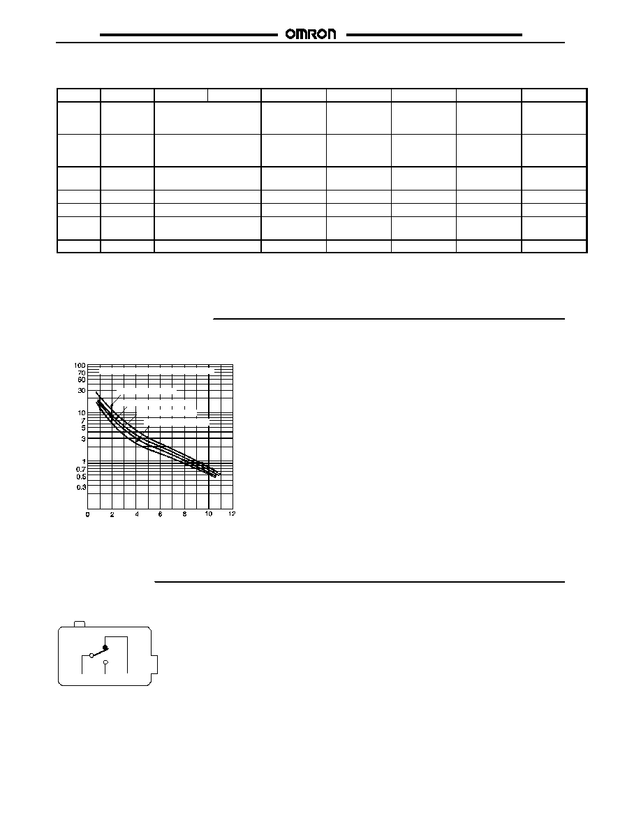
Engineering Data
J
ELECTRICAL LIFE EXPECTANCY
Lif
e
ex
pec
t
anc
y
(
x
1
0
oper
at
ions
)
6
Switching current (A)
Operating frequency: 20 operations/min
125 VAC (cos) = 1
125 VAC (cos) = 0.4
250 VAC (cos) = 1
250 VAC (cos) = 0.4
Operation
J
CONTACT FORM
COM
NO
NC
D4MC
D4MC
5
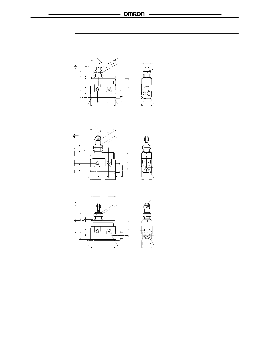
Dimensions
Unit: mm (inch)
J
LIMIT SWITCHES
D4MC-5000
D4MC-5020
D4MC-5040
Note: 1. Stainless steel plunger
2. The length of the imperfect
threads is 1.5 mm maximum.
Note: 1. Stainless steel roller
2. The length of the imperfect
threads is 1.5 mm maximum.
Note: 1. Stainless steel roller
2. The length of the imperfect
threads is 1.5 mm maximum.
M12 x 1 mounting screw
Two hexagon nuts
(thickness: 3
width: 17)
Two, 4.3�0.1 dia.
mounting holes
Seal
rubber
Terminal
protective
cover
22 max.
(0.87)
(See
Note 2.)
(See Note 1.)
8.4 dia.
12.7 dia. � 5 (See Note 1.)
(See
Note 2.)
M12 x 1 mounting screw
Two hexagon nuts
(thickness: 3
width: 17)
12.7 dia. � 5
(See Note 1.)
M12 x 1 mounting screw
Two hexagon nuts
(thickness: 3
width: 17)
Terminal
protective
cover
Two, 4.3�0.1 dia.
mounting holes
Seal
rubber
Terminal
protective
cover
Two, 4.3�0.1 dia.
mounting holes
Seal
rubber
16
dia.
25
(0.98)
53.4
(2.10)
23.3
(0.92)
55
(2.17)
23.3
(0.92)
18.3
SR11.9
21 x 21
53.4
(2.10)
21.7
(0.85)
14
15.8
PT
OP
PT
OP
PT
OP
15.5
53.4
(2.10)
23.3
(0.92)
25
(0.98)
22 max.
(0.87)
18.3
7
7
15
15
21.7
(0.85)
21 x 21
16
dia.
55
(2.17)
10
23
(0.91)
10
23
(0.91)
25.4� 0.15
(1.0� 0.006)
25.4� 0.15
(1.0� 0.006)
14
16
dia.
15
21.7
(0.85)
21 x 21
14
25
(0.98)
22 max.
(0.87)
18.3
7
15.5
23
(0.91)
10
25.4� 0.15
(1.0� 0.006)
(See
Note 2.)
D4MC
D4MC
6
26.5
(1.04) 22.5
(0.89)
55
(2.17)
21.7
(0.85)
D4MC-1000
Note: Stainless steel lever
t = 1 (See Note.)
Terminal
protective
cover
Two, 4.3�0.1 dia.
mounting holes
Seal rubber
D4MC-2000
12.7 dia. � 5
(See Note 2.)
Terminal
protective
cover
Two, 4.3�0.1 dia.
mounting holes
Seal
rubber
t = 1
(See Note 1.)
Note: 1. Stainless steel lever
2. Plastic roller
22 max.
(0.87)
19.5
(0.77)
53.4
(2.10)
34.7
(1.37)
21 x 21
25.4� 0.15
(1.0� 0.006)
25.4� 0.15
(1.0� 0.006)
21 x 21
10
Note: Unless otherwise specified, a tolerance of �0.4 mm applies to all dimensions.
14
15
6.4
OP FP
18.3
7
26.5
(1.04) 22.5
(0.89)
55
(2.17)
21.7
(0.85)
22 max.
(0.87)
19.5
(0.77)
53.4
(2.10)
34.7
(1.37)
10
14
15
OP FP
18.3
7
55
(2.17)
D4MC-1020
Note: Stainless steel lever
t = 1 (See Note.)
Terminal
protective
cover
Two, 4.3�0.1 dia.
mounting holes
Seal rubber
22 max.
(0.87)
22.5
(0.89)
21.7
(0.85)
14
10
25.4� 0.15
(1.0� 0.006)
34.7
(1.39)
26.5
(1.04)
53.4
(2.10)
15
18.3
7
19.5 OP
FP
6.4
21 x 21

D4MC
D4MC
7
Unit: mm (inch)
D4MC-2020
Note: 1. Stainless steel lever
2. Plastic roller
t = 1
(See Note 1.)
12.7 dia. � 7.5
(See Note 2.)
Terminal
protective
cover
Two, 4.3�0.1 dia.
mounting holes
Seal
rubber
21 x 21
25.4�0.15
(1.0� 0.006)
26.5
(1.04) 22.5
(0.89)
55 (2.17)
21.7
(0.85)
22 max.
(0.87)
19.5
(0.77)
53.4
(2.10)
34.7
(1.37)
10
14
15
OP FP
18.3
7
34.7 (1.37)
22.5
(0.89)
D4MC-3030
Mounting Holes
Two 4.3 dia. mounting holes or
M4 screw holes
25.4 � 0.15
(1.0 � 0.006)
Note: 1. Stainless steel lever
2. Plastic roller
12.7 dia. � 7.5
(See Note 2.)
t = 1
(See Note 1.)
Terminal
protective
cover
Two, 4.3�0.1 dia.
mounting holes
Seal
rubber
Angle of roller
swing: 90�
21.7
(0.85)
21 x 21
19.5
(0.77)
25.4�0.15
(1.0� 0.006)
22 max.
(0.87)
26.5
(1.04)
53.4 (2.10)
Note: Unless otherwise specified, a tolerance of �0.4 mm applies to all dimensions.
15
10
14
OP
FP
18.3
7
55 (2.17)

D4MC
D4MC
8
Customized Models
Molded Terminal Model
J
ORDERING INFORMATION
The molded terminal model is available with right-hand, left-hand and underside leads and is recommended for use in applications where
the switch is exposed to dust, oil, or moisture.
(2)
(3)
(1)
When placing your order for the switch, specify the required length of V.S.F. or V.C.T. cable in addition to the model number of the switch.
Example:
Standard type: D4MC-5040
Location of lead outlet: Underside
Length of lead: 1 m (V.C.T. lead)
When placing your order for the above switch, specify the model number as D4MC-5043 (V.C.T 1 m)
Suffix by Location of lead Outlet
Location of lead outlet
Part number
COM, NC, and NO
COM and NC
COM and NO
Right-hand
D4MC-j
j
j
jj
j
j
jj
j
j
j
1
D4MC-j
j
j
jj
j
j
jj
j
j
j
4
D4MC-j
j
j
jj
j
j
jj
j
j
j
7
Left-hand
D4MC-j
j
j
jj
j
j
jj
j
j
j
2
D4MC-j
j
j
jj
j
j
jj
j
j
j
5
D4MC-j
j
j
jj
j
j
jj
j
j
j
8
Underside
D4MC-j
j
j
jj
j
j
jj
j
j
j
3
D4MC-j
j
j
jj
j
j
jj
j
j
j
6
D4MC-j
j
j
jj
j
j
jj
j
j
j
9
Leads Supplied
Leads
Nominal
cross-sectional area
Finished outside diameter
Terminal
connections
Standard length
V.S.F. (Single-conductor vinyl
cable)
1.25 mm
2
3.1 mm dia.
Black: COM
White: NO
R d
NC
1, 3, 5 m
V.C.T. (Vinyl cabtyre cable)
1.25 mm
2
Double conductor: 9.6 mm dia.
Triple conductor: 10.5 mm dia.
Red: NC

D4MC
D4MC
Cat. No. CEDSAX4 11/01 Specifications subject to change without notice. Printed in U.S.A.
OMRON ELECTRONICS LLC
One East Commerce Drive
Schaumburg, IL 60173
NOTE: DIMENSIONS SHOWN ARE IN MILLIMETERS. To convert millimeters to inches divide by 25.4.
1-800-55-OMRON
OMRON CANADA, INC.
885 Milner Avenue
Scarborough, Ontario M1B 5V8
416-286-6465
R
OMRON ON--LINE
Global -- http://www.omron.com
USA -- http://www.omron.com/oei
Canada -- http://www.omron.com/oci