 | –≠–ª–µ–∫—Ç—Ä–æ–Ω–Ω—ã–π –∫–æ–º–ø–æ–Ω–µ–Ω—Ç: D8M-D82 | –°–∫–∞—á–∞—Ç—å:  PDF PDF  ZIP ZIP |
Document Outline
- First Page
- Ordering Information
- Specifications
- Dimensions
- Contact Information

Solid State Pressure Sensors
D8M
1
Solid State Pressure Sensors
D8M
Solid State Pressure Sensors with
Analog, Pulse or Frequency Outputs
∑ Compact housing measures 30L x 30W x 12.4H mm.
∑ Accept 4 mm OD tubing (D8M-A1, -R1); 3 mm OD tubing
for (D8M-D1, -D2), 6 mm OD tubing for D8M-D82.
∑ Chemical-resistant plastic (PBT) body.
∑ Metal shield mounted version (D8M-D82) available.
∑ IP40 enclosure rating for embedded applications.
∑ Pre-wired and PCB mounting models available.
Ordering Information
Operating pressure
range
Output signal
Output frequency
Power supply
voltage
Withstand pressure
Model
0 to 4.9 kPa
(0 to 0.71 psi)
Analog,
15 to 1247 mV
--
2.2
±0.1 VDC
58.8 kPa (8.53 psi) for 3
minutes
D8M-A1
0 to 5.88 kPa
(0 to 0.85 psi)
Pulse count,
1 pulse/9.81 Pa
(1/0.0014 psi)
--
2.2 to 3.4 VDC with
regulator
58.8 kPa
(8.53 psi) for 3 minutes
D8M-D1
0 to 5.88 kPa
(0 to 0.85 psi)
Pulse count,
1 pulse/9.81 Pa
(1/0.0014 psi)
--
2.2 to 3.4 VDC with
regulator
58.8 kPa
(8.53 psi) for 3 minutes
D8M-D2
0 to 4.9 kPa
(0 to 0.71 psi)
Pulse count,
1 pulse/9.81 Pa
(1/0.0014 psi)
--
2.2 to 3.4 VDC with
regulator
19.6 kPa (2.84 psi) for 5
minutes
D8M-D82
0 to 196.13 Pa
(0 to 0.028 psi)
Frequency,
1 kHz/9.81 Pa
(1 kHz/0.0014 psi)
80 to 300 kHz
4.2 to 5.5 VDC with
regulator
3 kPa (0.435 psi) for 10
seconds
D8M-R1
2
Solid State Pressure Sensors
D8M
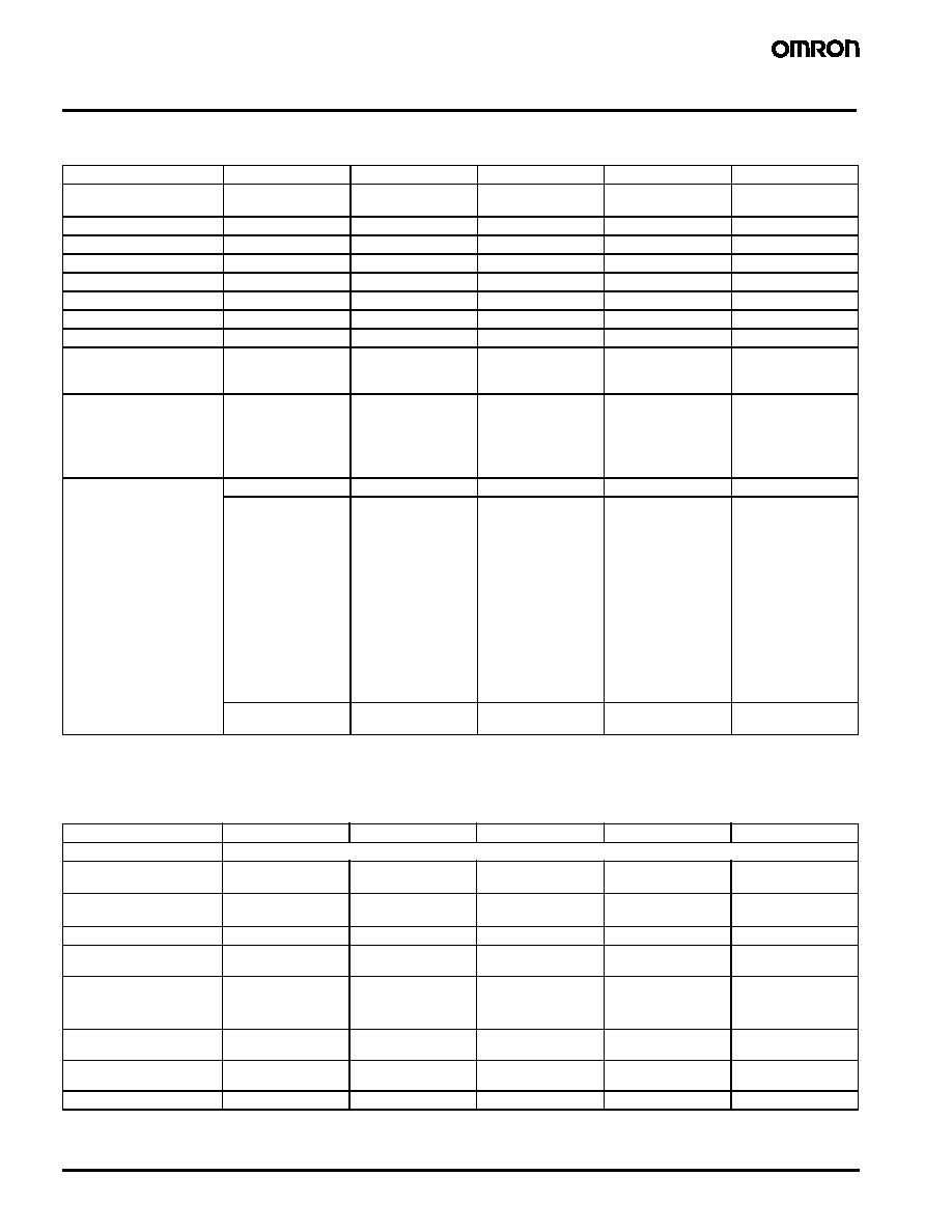
Specifications
Electrical Ratings
Note: 1. Output voltage (mV) = Supply voltage V (2.2) x (2.464 x Pressure (kPa)/9.8 x 1000 + 15)
2. Values measured during and after testing.
Operating Characteristics
Note: With no icing or condensation
Item
D8M-A1
D8M-D1
D8M-D2
D8M-D82
D8M-R1
Power supply voltage
2.2
±0.1 VDC
2.2 to 3.4 VDC with
regulator
2.2 to 3.4 VDC with
regulator
2.2 to 3.4 VDC with
regulator
4.2 to 5.5 VDC with
regulator
Current consumption
2.5 mA max.
25 mA max.
25 µA
100 mA
±5% at 3 VDC 10 mA max.
Load resistance
1 M
min.
--
--
--
--
Output resistance
500
max.
--
--
--
--
Leakage current
1 mA or less
1 mA or less
1 mA or less
1 mA or less
1 mA or less
Output voltage
15 to 1247 mV
--
--
--
--
Output pulses
--
--
--
--
80 to 300 kHz
Output resolution
(Note 1)
1 pulse/9.81 Pa
1 pulse/9.81 Pa
1 pulse/9.81 Pa
1 kHz/9.81 Pa
Output voltage rate of
change with resistance
load change
1 M
or more into 30
k
is made within
2.5%
--
--
--
--
Output voltage by input
pressure
0.98 kPa = 261 mV
1.96 kPa = 508 mV
3.73 kPa = 951 mV
4.9 kPa = 1247 mV
(Note 1)
--
--
--
--
Operating characteristics
±62 mV initial
--
--
--
--
±37 mV during test
and after
0 kPa = 30 pulses
0.59 kPa = 60
±32
pulses
1.96 kPa = 200
±24
pulses
3.73 kPa = 380
±24
pulses
5.39 kPa = 530
±82
pulses
(Note 2)
0 kPa = 30 pulses
0.59 kPa = 60
±32
pulses
1.96 kPa = 200
±24
pulses
3.73 kPa = 380
±24
pulses
5.39 kPa = 550
±82
pulses
(Note 2)
0 kPa = 30 pulses
0.15 kPa = 45
±30
pulses
2 kPa = 204
±15
pulses
4 kPa = 438
±46
pulses
0 Pa =
180
±100 kHz;
Incremental change
from 0 value:
49.03 Pa =
5
±0.9 kHz
73.55 Pa =
7.5
±1.0 kHz
147.10 Pa =
15
±0.8 kHz
196.13 Pa =
20
±1.4 kHz
(Note 2)
±62 mV temperature
influence
--
--
--
--
Item
D8M-A1
D8M-D1
D8M-D2
D8M-D82
D8M-R1
Pressure type
Gauge
Pressure range
0 to 4.9 kPa
(0 to 0.71 psi)
0 to 5.88 kPa
(0 to 0.85 psi)
0 to 5.88 kPa
(0 to 0.85 psi)
0 to 4.9 kPa
(0 to 0.71 psi)
0 to 196.13 Pa
(0 to 0.028 psi)
Withstand pressure
5.88 kPa for 3
minutes
58.8 kPa for 3
minutes
58.8 kPa for 3
minutes
19.6 kPa for 5
minutes
3 kPa for 10
seconds
Repeatability/hystersis
±0.5% FS
±0.5% FS
NA
±0.5% FS
±0.5% FS
Non-linearity
characteristics
--
--
--
±2% FS max.
±2% FS max.
Response time
3.0 ms
2.5 ms (pressure)
18 ms max. (switch)
100 ms (discharge)
3 ms (pressure)
32 ms max. (switch)
250 ms (discharge)
1.5 ms (pressure)
30 ms max. (switch)
45 ms (discharge)
3 seconds max.
Operating temperature
(Note)
-30
∞ to 70∞C
-30
∞ to 70∞C
-30
∞ to 70∞C
-10
∞ to 60∞C
-20
∞ to 70∞C
Storage temperature
(Note)
-40
∞ to 80∞C
-40
∞ to 80∞C
-40
∞ to 80∞C
-20
∞ to 70∞C
-30
∞ to 80∞C
Operating humidity
25 to 95%
25 to 95%
25 to 95%
25 to 95%
25 to 95%
Solid State Pressure Sensors
D8M
3
Environmental Characteristics
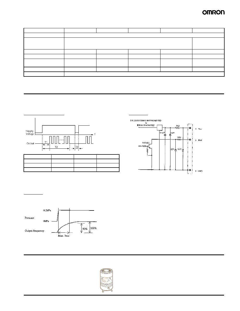
Operation
Response Timing Charts
D8M-D1, D2, D82
Legend: T1, Pressure measurement time
T2, Response time
T3, Electrical discharge time
D8M-R1
Interface Circuit Diagram
D8M-R1
Application Examples
Compact D8M solid state pressure sensors provide reliable detection
for gas and air inflow for burner controls in water heaters, furnaces
and other gas-fired devices. They can also be used in
gas usage meters.
Item
D8M-A1
D8M-D1
D8M-D2
D8M-D82
D8M-R1
Insulation resistance
100 m
min., 250 VDC between lead terminals and the base
Dielectric strength
250 VAC, 50/60 Hz for 1 minute between lead terminals and the base
500 VAC, 50/60 Hz for
1 minute between ter-
minals and the base
Degree of protection
NA
IP40
IP40
IP40
IP40
Pressure port
4 mm OD
3 mm OD
3 mm OD
6 mm OD
4 mm OD
Connection method
Solder on PC boards
Wiring connector on
top
Wiring connector on
top
Three AWG26 wires,
115 mm long
Wiring connector on
bottom
Weight
NA
NA
NA
NA
NA
Material
PBT (polybutylene terephthalate)
Model
T1
T2
T3
D8M-D1
2.5 ms min.
18 ms max.
100 ms min.
D8M-D2
3.0 ms min.
32 ms max.
250 ms min.
D8M-D82
1.5 ms min.
30 ms max.
45 ms max.
Response time to 90% of 0.2kPa
Max. 3 seconds (excluding time for pressure change)

4
Solid State Pressure Sensors
D8M
Dimensions
Unit: mm (inch)
D8M-A1
D8M-D1
30 (1.18)
23 (0.92)
±0.2
30 (1.18)
23 (0.92)
±0.2
Two 3.2 (0.13) dia.
mounting holes
17.7 (0.70)
10.1 (0.40)
4 (0.16) OD
LOT NUMBER
TYPE NAME
4 (0.16) OD
18.8 (0.74)
18.6 (0.73)
11.6 (0.46)
2 (0.08)
5 (0.20)
1.6 (0.06)
4.4 (0.17)
7 (0.28)
Two, 1.5 (0.06) dia.
standoff pins
Three, 0.635 (0.025)
square terminal leads
GND
V
OUT
V
CC
Two, M3 holes
23 (0.91)
±0.1
Two, 3 (0.12) dia.
10.7 (0.42)
23 (0.91)
±0.1
5.08 (0.20)
5.08 (0.20)
15.6 (0.61)
±0.01
Terminal Arrangement
(Top View)
Mounting Holes
(Top View)
2 (0.08)

Solid State Pressure Sensors
D8M
5
D8M-D2
D8M-D82