Document Outline
- Front Page
- Ordering Information
- Specifications
- Nomenclature
- Operation
- Dimensions
- Installation
- Contacting Omron
69
E2CA
E2CA
Sensor type
Shielded
3 m (9.8 ft) cable
E2CA-X1R5A
E2CA-X2A
E2CA-X5A
E2CA-X10A
5 m (16.4 ft) cable
E2CA-X1R5A-5M
E2CA-X2A-5M
E2CA-X5A-5M
E2CA-X10A-5M
Size
M8
M12
M18
M30
Nominal sensing
0.3 to 1.5 mm
0.4 to 2.0 mm
1 to 5 mm
2 to 10 mm
distance
(0.01 to 0.06 in)
(0.02 to 0.08 in)
(0.04 to 0.20 in)
(0.08 to 0.39 in)
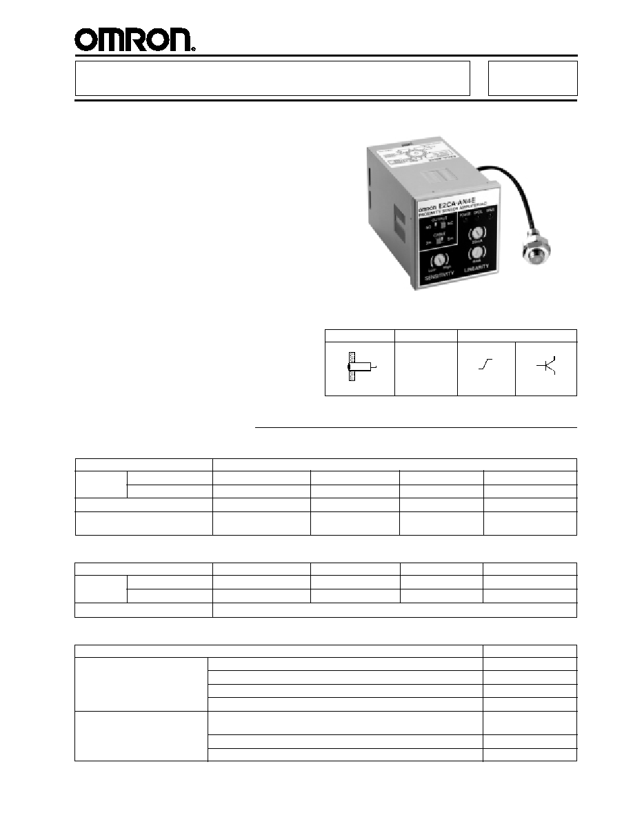
Threaded Cylindrical Inductive Sensor with
Separate Amplifier Provides Precision
Linear Analog Output and a Discrimination
Output
s
Linear 4 to 20 mA output for target to sensor
distance
s
Position measurements accurate to
�
0.0006 mm with 0.05% full scale resolution
s
Adjustable setpoint controls switching output
rated 100 mA is NO/NC selectable
s
Amplifier has power ON, target detected,
and discrimination output indicators
s
AC amplifier has universal voltage rating
90 to 264 VAC
s
DC amplifier rated 10 to 30 VDC
s
Sensors available in standard 8, 12, 18,
30 mm sizes with sensing distances
up to 10 mm
Ordering Information
s
SENSOR
Required sensor
E2CA-X1R5A/-5M
E2CA-X2A/-5M
E2CA-X5A/-5M
E2CA-X10A/-5M
AC power supply
E2CA-AN4C
E2CA-AN4D
E2CA-AN4E
E2CA-AN4F
DC power supply
E2CA-AL4C
E2CA-AL4D
E2CA-AL4E
E2CA-AL4F
Outputs
Linear output, 4 to 20 mA; Switching output, selectable NO or NC transistor
s
AMPLIFIER
Special-Purpose Proximity Sensor
E2CA
Part
number
Part
number
Sensing
Supply voltage
Output
90 to 264 VAC,
50/60 Hz
amplifier or
10 to 30 VDC
amplifier
1.5, 2, 5, 10 mm
4 to 20 mA
100 mA, 40 VDC
Description
Part number
Mounting brackets for sensors
Fits M8 size sensors
Y92E-B8
Fits M12 size sensors
Y92E-B12
Fits M18 size sensors
Y92E-B18
Fits M30 size sensors
Y92E-B30
Sockets for amplifiers
Combination bottom surface and track mounting socket with
P2CF-11
screw terminals
Back mounting socket with screw terminals for panel mount applications P3GA-11
Circuit board socket with solder terminals
PL-11
s
ACCESSORIES
(This table continues on the following page.)
E2CA
E2CA
70
Part number
E2CA-X1R5A/-5M
E2CA-X2A/-5M
E2CA-X5A/-5M
E2CA-X10A/-5M
Sensor type
Inductive
Body
Size
M8
M12
M18
M30
Type
Shielded
Required amplifier
E2CA-AL4C or
E2CA-AL4D or
E2CA-AL4E or
E2CA-AL4F or
E2CA-AN4C
E2CA-AN4D
E2CA-AN4E
E2CA-AN4F
Detectable object type
Metallic objects
Effective maximum
1.5 mm (0.06 in)
2 mm (0.08 in)
5 mm (0.20 in)
10 mm (0.39 in)
sensing distance
(with standard target)
Usable sensing range
0.3 to 1.5 mm
0.4 to 2.0 mm
1 to 5 mm
2 to 10 mm
(with standard target)
(0.01 to 0.06 in)
(0.02 to 0.08 in)
(0.04 to 0.20 in)
(0.08 to 0.39 in)
Standard target size
8 x 8 x 1 mm
12 x 12 x 1 mm
18 x 18 x 1 mm
30 x 30 x 1 mm
(mild steel, L x W x H)
(0.32 x 0.32 x 0.04 in)
(0.47 x 0.47 x 0.04 in)
(0.71 x 0.71 x 0.04 in)
(1.18 x 1.18 x 0.04 in)
Response frequency
10 kHz
5 kHz
3 kHz
Indicators
Not provided
Materials
Housing
Nickel-plated brass
Sensing face Plastic, acrylonitoryl butadiene styrene
Cable sheath Plastic, polyethylene
Mounting
Two lock washers and
Two lock washers and
Two lock washers and
Two lock washers and
M8 nuts included.
M12 nuts included.
M18 nuts included.
M30 nuts included.
Bracket Y92E-B8
Bracket Y92E-B12
Bracket Y92E-B18
Bracket Y92E-B30
optional.
optional.
optional.
optional.
Connections Prewired
2-conductor shielded cable: 3 m (9.8 ft) length (E2CA-X
A)
5 m (16.4 ft) length (E2CA-X
A-5M)
Weight with cable
40 g (1.4 oz.)
60 g (2.1 oz.)
140 g (5.0 oz.)
160 g (5.7 oz.)
UL
--
NEMA
1, 4, 6, 12, 13
IEC 144
IP67
Approvals
UL
--
CSA
--
Ambient operating
-25
�
to 70
�
C (-13
�
to 158
�
F)
-10
�
to 55
�
C
temperature
(14
�
to 131
�
F)
Vibration
10 to 55 Hz, 1.5 mm (0.06 in) double amplitude
10 to 25 Hz, 2 mm (0.08 in)
double amplitude
Shock
Approx. 50 G
Approx. 10 G
Description
Part number
Panel mounting adapter for amplifier
Y92F-30
Protective covers for amplifier
Hard plastic cover protects amplifiers from dust, dirt and water drip
Y92A-48
Soft plastic cover protects amplifier from dust, dirt and water drip
Y92A-48D
Mounting track
DIN rail, 50 cm (1.64 ft) length
PFP-50N
DIN rail, 1 m (3.28 ft) length
PFP-100N
End plate
PFP-M
Spacer
PFP-S
Specifications
s
REPLACEMENT PARTS
Description
Part number
Fits M8 size sensors (supplied with each sensor)
M8-MHWS
Fits M12 size sensors (supplied with each sensor)
M12-MHWS
Fits M18 size sensors (supplied with each sensor)
M18-MHWS
Fits M30 size sensors (supplied with each sensor)
M30-MHWS
s
SENSOR
Specifications Table -- continued from previous page
Mounting hardware
includes one
pair of metal
nuts and washers
Enclosure
ratings
71
E2CA
E2CA
Part number
E2CA-A
4C
E2CA-A
4D
E2CA-A
4E
E2CA-A
4F
AC types
90 to 264 VAC, 50/60 Hz (E2CA-AN4
)
DC types
10 to 30 VDC (E2CA-AL4
)
AC types
60 mA max. (E2CA-AN4
)
DC types
70 mA max. (E2CA-AL4
)
Required sensor
E2CA-X1R5A
E2CA-X2A
E2CA-X5A
E2CA-X10A
Output range
4 to 20 mA
Resolution
0.05% to full scale
Linearity
�
2.0% of full scale
�
1.5% of full scale
�
2.0% of full scale
Response frequency
10 kHz
5 kHz
3 kHz
Adjustment
4 mA
Adjustment to 4 mA at 20% of effective maximum detecting distance
20 mA
Adjustment to 20 mA at effective maximum detecting distance
Operation mode
NO or NC, switch selectable
Detecting distance
Adjustable (within sensor's "Usable Detecting Range")
sensitivity
Differential travel
Fixed, 1 to 5% of detecting distance
Type
Transistor, SPST
Max. load
100 mA, 40 VDC
Max. on-state 2 VDC
voltage drop
Response frequency
3 kHz
1.5 kHz
1 kHz
Switching output
Not provided
short-circuit
DC power supply
Provided
reverse polarity
Weld-field immunity
Not provided
RFI immunity
Not provided
Indicators
Power ON (POWER), Linear Range (SPAN), and Switching Output ON (OPER)
Materials
Housing
Plastic
Mounting
Requires P2CF-11, P3GA-11 or PL11 sockets (not included); order separately from
Accessories.
Adapter Y92F-30 for panel mounting the amplifier (optional); order separately from
Accessories.
Connections
Plated steel screw terminals (P2CF-11 and P3GA-11 sockets); Solder terminals (PL11 socket)
AC types
250 g (8.8 oz.)
DC types
120 g (4.2 oz.)
UL
--
NEMA
1
IEC 144
IP40
Approvals
UL
--
CSA
--
Ambient operating temperature
�10
�
to 55
�
C (�14
�
to 131
�
F)
Vibration
10 to 25 Hz, 2 mm (0.08 in) double amplitude
Shock
Approx. 10 G
s
AMPLIFIER
Linear
output
characteristics
Current
consumption
Switching
output
characteristics
Supply
voltage
Control
output
Circuit
protection
Weight without
socket
Enclosure
ratings
E2CA
E2CA
72
Classification
Function
Linear output
An analog 4 to 20 mA output signal proportional to the distance from the target to the face of the sensor
within the range of the 4 mA linear setpoint to the 20 mA setpoint.
Switching output
A 100 mA, 40 VDC rated transistor output (separate power source required) adjustable within the range of the
4 mA linear setpoint and 20 mA linear setpoint.
Power ON
Red LED illuminated when amplifier is connected to power source and energized.
Operation
Red LED illuminated when the target is present within the range from the minimum sensing distance to the
target setpoint distance.
Span
Green LED illuminated when the target is present within the range of the 4 mA linear setpoint and the 20 mA
linear setpoint.
Cable length selector
Set to the length of cable (3 or 5 meters) supplied on the sensor head.
switch
4 mA linear adjustment
Used to set the analog output at 4 mA when the target is at 20% of the rated sensing distance.
Adjustment method 1.
20 mA linear adjustment
Used to set the analog output at 20 mA when the target is at 100% of the rated sensing distance.
Adjustment method 1.
Sensitivity
Used to set the target distance that turns on the switching output.
Mode selector switch
Determines the logic of the switching output circuit. In the NO position, the target turns on when the target is
present between the minimum sensing distance and the target setpoint distance. In the NC position, the
switching output turns on when the target is beyond the target setpoint distance.
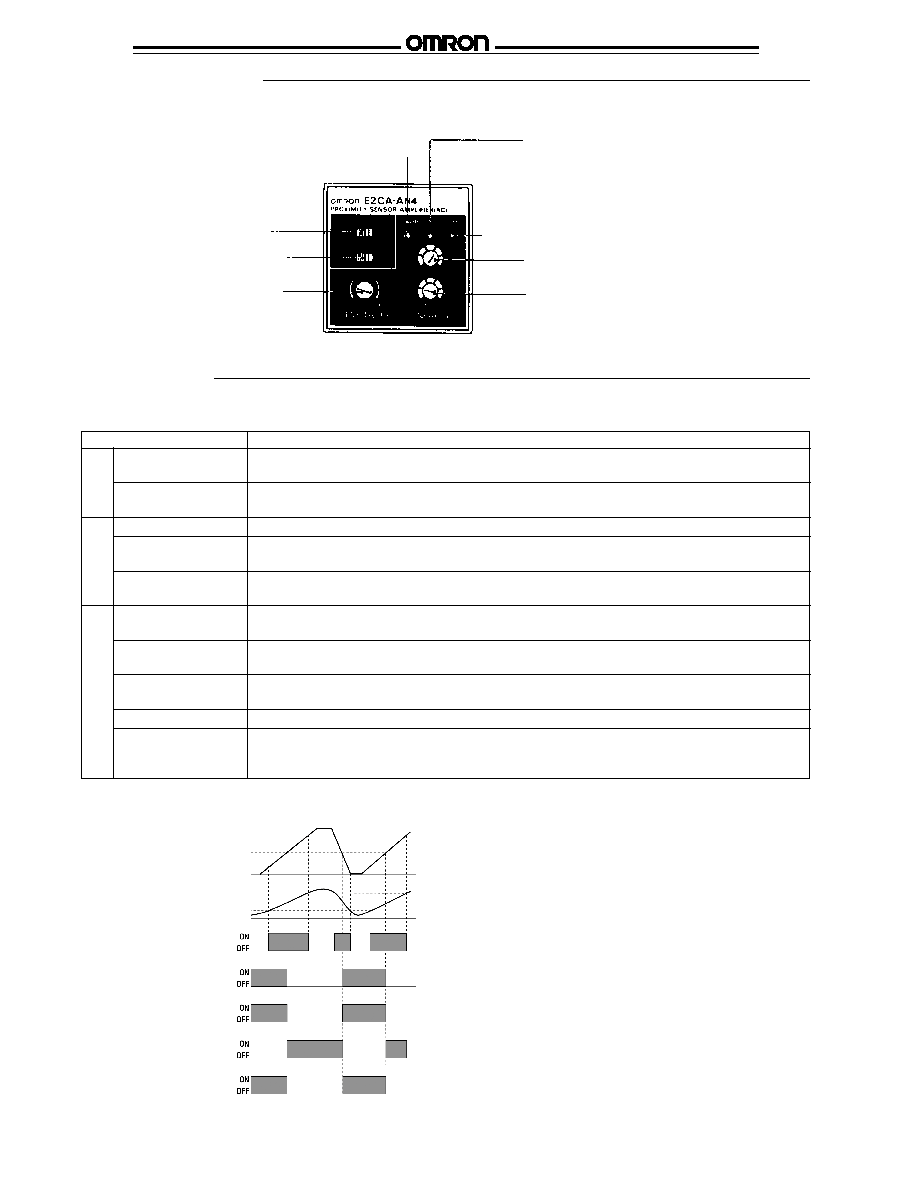
OPER. indicator (Red LED)
Illuminates when the target is
present within the range from
the minimum sensing distance
to the target setpoint distance
SPAN indicator (Green LED)
Indicates the linear area of the output current
Linear output current adjustment (20 mA)
Linear output current adjustment (4 mA)
POWER indicator (Red LED)
Illuminates when energized
Mode selector switch
Selector switch for cable
length compensation
SENSITIVITY adjustment
Adjusts the target setpoint
distance for switching output
s
FUNCTION -- AMPLIFIER
s
AMPLIFIER
s
TIMING CHART
100% rated distance
Target setpoint distance
20% rated distance
Distance of
target
20 mA
4 mA
Linear
output
SPAN indicator
Mode selector
� NO position
� NC position
Switching
output
Operator
indicator
Switching
output
Operator
indicator
Nomenclature
Operation
O
U
T
P
U
T
I
N
D
I
C
A
T
O
R
S
A
D
J
U
S
T
M
E
N
T
S
73
E2CA
E2CA
s
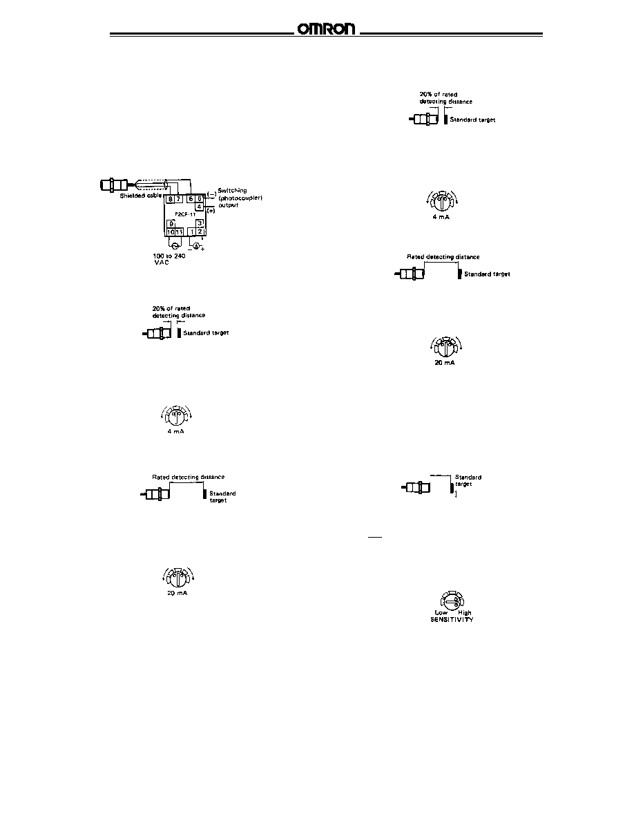
LINEAR OUTPUT ADJUSTMENTS
Choose one of the two adjustment methods for setting the
LINEARITY adjuster. Adjustment of the 4 mA and
20 mA LINEARITY adjusters must be performed with the
standard target at positions of 20% and 100% of the rated
detecting distance away from the sensor.
Linearity Adjustment Method 1
1. Connect an ammeter across terminals 1 and 2. The
illustration shows the sensor connected to an amplifier
through socket P2CF-11.
2. Place the standard target at 20% of the rated detecting
distance away from the sensor unit.
3. Turn the 4 mA LINEARITY adjuster slowly clockwise (to
increase the output current) or counterclockwise (to
decrease the output current). Set the adjuster to a position
that reads 4 mA output on the ammeter.
4. Place the standard target at the rated detecting distance.
5. Turn the 20 mA LINEARITY adjuster slowly clockwise (to
increase the output current) or counterclockwise (to
decrease the output current). Set the adjuster to a position
that reads 20 mA output on the ammeter.
6. To fine tune the adjustment accuracy of the output current,
repeat the adjustment steps for 4 mA and 20 mA
LINEARITY adjusters.
Linearity Adjustment Method 2
1. Set the standard target at 20% of the rated detecting
distance away from the sensor.
2. Turn the 4 mA LINEARITY adjuster counterclockwise so that
the SPAN indicator remains OFF. Then slowly turn the
adjuster clockwise until the indicator illuminates. Stop
turning the adjuster at the position where the SPAN
indicator illuminates.
3. Set the standard target at the rated detecting distance away
from the sensor.
4. Slowly turn the 20 mA LINEARITY adjuster clockwise until
the SPAN indicator goes OFF. Then turn the adjuster
counterclockwise until the indicator illuminates. Stop turning
the adjuster when the SPAN indicator illuminates.
s
SENSITIVITY ADJUSTMENTS
S
0.8
Place the standard target at the specified position. If the target
moves in parallel with the surface of the sensor unit, make the
adjustment after determining the position using the following
procedure.
1. Adjust the linear output according to Adjustment Method 1
or 2.
2. Calculate detecting distance X using the following formula:
X =
S = setting distance
3. Adjust the distance between the sensor and the object to
be detected to distance X.
Slowly turn the SENSITIVITY adjuster clockwise (toward HIGH)
and stop turning when the OPER. indicator illuminates. Move
the target to confirm that the OPER. indicator illuminates when
the object to be detected is at the specified position and that
the indicator goes OFF when the target is moved away from
that position.
If the target moves in parallel with the surface of the sensor
unit, place the sensor at distance S.