 | –≠–Ľ–Ķ–ļ—ā—Ä–ĺ–Ĺ–Ĺ—č–Ļ –ļ–ĺ–ľ–Ņ–ĺ–Ĺ–Ķ–Ĺ—ā: E2C-T | –°–ļ–į—á–į—ā—Ć:  PDF PDF  ZIP ZIP |
Document Outline
- First Page
- Ordering Information
- Specifications
- Operation
- Nomenclature
- Engineering Data
- Dimensions
- Installation
- Precautions
- Contacting Omron

R
Miniature Inductive Prox
E2C-T
Proximity Sensor with Separate
Amplifier for Detecting All Metals
H
Incorporates Easy-to-Use Teaching
Function for Simple Setup and
Accurate, Reliable Sensing
H
Three teaching modes allow easy setup
and precise detection ability for all metal
targets
H
Slim, 10-mm wide, amplifier unit allows
superior mounting flexibility
H
Can be used with many existing sensor
heads in the E2C family
Ordering Information
J
SENSOR HEADS
Size
Sensing distance
All temperature ranges
0įC to 40įC (32įF to 104įF)
Part number
2 dia.
3.5 dia.
3.8 dia.
M5
5.4 dia.
M8
Un-shielded (See Note.)
Shielded
0.5 mm
0.8 mm
0.8 mm
1 mm
1 mm
1.5 mm
0.7 mm
1.2 mm
1.2 mm
1.5 mm
1.5 mm
2 mm
E2C-CR5B2
E2C-CR8A
E2C-CR8B
E2C-X1A
E2C-C1A
E2C-X1R5A
Type
Note: The E2C-CR5B2 with shielded construction cannot be embedded in metal.
J
AMPLIFIER UNIT
Item
Part number
Amplifier
E2C-T11
Amplifier with built-in connection (for CompoBus/S)
E2C-T16
Mounts to the Sensor Terminals easily for CompoBus/S use.
E2C-T11
E2C-T16

E2C-T
E2C-T
2
Specifications
J
E2C-T1j AMPLIFIER UNITS
Item
Sensor head
Item
E2C-CR5B2
E2C-CR8A
E2C-CR8B
E2C-X1A
E2C-C1A
E2C-X1R5A
Supply voltage
12 to 24 VDC Ī 10% (operation: 10 to 26.4 VDC), ripple (p-p): Ī10% max.
Current consumption
50 mA max.
Sensing
distance
adjustment
(S
Setting distance for teaching without
sensing target
(See Note 2.)
0.4 mm min.
0.72 mm min.
0.9 mm min.
1.35 mm min.
j
range (See
Note 1.)
Setting distance for
teaching with and
without target
0įC to 40įC
(32įF to 104įF)
0.1 to 0.7 mm
0.16 to 1.2 mm
0.2 to 1.5 mm
0.3 to 2 mm
without target
object or
positioning
teaching
0įC to 55įC
(32įF to 131įF)
0.1 to 0.5 mm
0.16 to 0.8 mm
0.2 to 1.0 m
0.3 to 1.5 mm
Temperature influence
Ī25% max. of
sensing distance at
23įC in the
temperature range
of 0įC to 55įC
(32įF to 131įF)
Ī10% max. of sensing distance at 23įC in the
temperature range of 0įC to 55įC (32įF to 131įF)
Ambient temperature
Operating
0įC to 55įC (32įF to 131įF) with no icing
Ambient humidity
Operating
35% to 95%
Differential travel
15% max. of
sensing distance
10% max. of sensing distance
Response time
Refer to the response frequency of the Sensor Heads (next page).
Control output
NPN open collector output of 100 mA max. at 26.4 V with a residual voltage of
1 V max.
NO/NC selectable
Cable length compensation
3 m
1, 2, or 3 m selectable
Indicators
Operation indicator (orange) and stability indicator (green)
Voltage influence
Ī1% max. of sensing distance within a range of 90% to 110% of the rated
power supply voltage
Insulation resistance
50 M min. at 500 VDC between current carrying parts and case
Dielectric strength
1,000 VAC (50/60 Hz) for 1 min between current carrying parts and case
Vibration resistance
Destruction: 10 to 55 Hz, 1.5-mm double amplitude for 2 hours each in X, Y,
and Z directions
Enclosure rating
IEC, IP50
Weight
Approx. 70 g
Note: 1. Perform positioning teaching within the stable sensing distance, or reset failures may result when the E2C-T is in operation. If a
fine-difference teaching is performed with and without a target object, reset failures may result when the E2C-T is in operation --
even if teaching is successful.
2. The above distances for teaching without a target object were measured without surrounding metal or background.
3. E2C-T16 can only be used with CompoBus/S system.

E2C-T
E2C-T
3
J
E2C-j SENSOR HEADS
Item
Sensor head
Item
E2C-CR5B2
E2C-CR8A
E2C-CR8B
E2C-X1A
E2C-C1A
E2C-X1R5A
Target object
Ferrous metal (Refer to Engineering Data for non-ferrous metal as target objects)
Standard target object
Iron: 5 x 5 x 1 mm
Iron: 8 x 8 x 1 mm
Stable sensing range (within whole
rated temperature range)
0 to 0.5 mm
(0 to 0.02 in)
0 to 0.8 mm
(0 to 0.03 in)
0 to 1 mm
(0 to 0.04 in)
0 to 1.5 mm
(0 to 0.06 in)
Stable sensing range at 0įC to 40įC
0 to 0.7 mm
(0 to 0.03 in)
0 to 1.2 mm
(0 to 0.05 in)
0 to 1.5 mm
(0 to 0.06 in)
0 to 2 mm
(0 to 0.08 in)
Response frequency (See Note 1.)
1 kHz
800 Hz
Ambient temperature
Operating: --10įC to
55įC (14įF to 131įF)
Operating: --25įC to 70įC (--13įF to 158įF) with no icing
Ambient humidity
Operating: 35% to 95%
Temperature influence
Ī25% max. of sensing
distance at 23įC in the
temperature range of
--10įC to 55įC
(14įF to 131įF)
Ī15% max. of sensing distance at 23įC in the temperature range of
--25įC to 70įC (--13įF to 158įF)
Vibration resistance
Destruction: 10 to 55 Hz, 1.5-mm double amplitude for 2 hours each in X, Y, and Z directions
Shock resistance
Destruction: 500 m/s
2
(approx. 50G) three times each in X, Y, Z directions
Enclosure rating
IEC60529 IP64
JEM IP64 (drip-proof)
IEC, IP67 (JEM IP67g, waterproof and oil-proof)
Connection cable length
(See Note 2.)
3-m shielded cable
3-m coaxial cable (standard length)
Weight with 3-m cable
Approx. 10 g
Approx. 40 g
Approx. 45 g
Approx. 50 g
Material
Case
Stainless steel
Brass
Material
Sensing surface
ABS resin
Cable
Polyethylene
Note: 1. The response frequency was measured by using standard target objects under the condition that the space between each pair
of adjacent target objects is double the width of a single target object and the setting distance is half the maximum sensing
distance.
2. The characteristic impedance of the coaxial cable for high-frequency use is 50 .

E2C-T
E2C-T
4
Operation
J
CONNECTION
Proximity Sensor
Shielded wire
NPN open collector output
J
OUTPUT CIRCUIT
12 to 24 VDC
0 V
Brown
Black
Blue
12 to 24 VDC
0 V
Blue
Black
Brown
39 V
100 mA max.
Load
Main
circuit
Control
output
J
TIMING CHARTS
Sensing distance
Approx. 107 %
Sensing distance
100 %
Approx. 93 %
Time
Control output
Output indicator (orange)
ON
OFF
ON
OFF
ON
OFF
STB (stability) indicator (green)
NO Setting
Control output
Output indicator (orange)
ON
OFF
ON
OFF
ON
OFF
STB (stability) indicator (green)
NC Setting
E2C-T
E2C-T
5
J
INDICATORS
The OUT indicator indicates the status of the control output transistor. The indicator will be ON when the transistor has control output (i.e.,
NPN open collector output).
If the operation selector is set to NO, the indicator will be ON when the target object is in the sensing distance range. If the operation se-
lector is set to NC, the indicator will be ON when the target object is not in the sensing distance range.
The STB (stability) indicator indicates the excess gain of object detection or non-detection. The indicator will be ON when the target object
is within approximately 93% of the sensing distance or at approximately 107% of the sensing distance or beyond.
OUT indicator (orange)
S
t
able
no-
s
ens
ing
a
r
e
a
S
t
able
s
ens
ing
a
r
e
a
Set to NC
Set to NO
ON
OFF
ON
OFF
ON
ON
OFF
STB (stability)
indicator (green)
Approx. 107% of sensing distance
Sensing distance
Approx. 93% of sensing distance
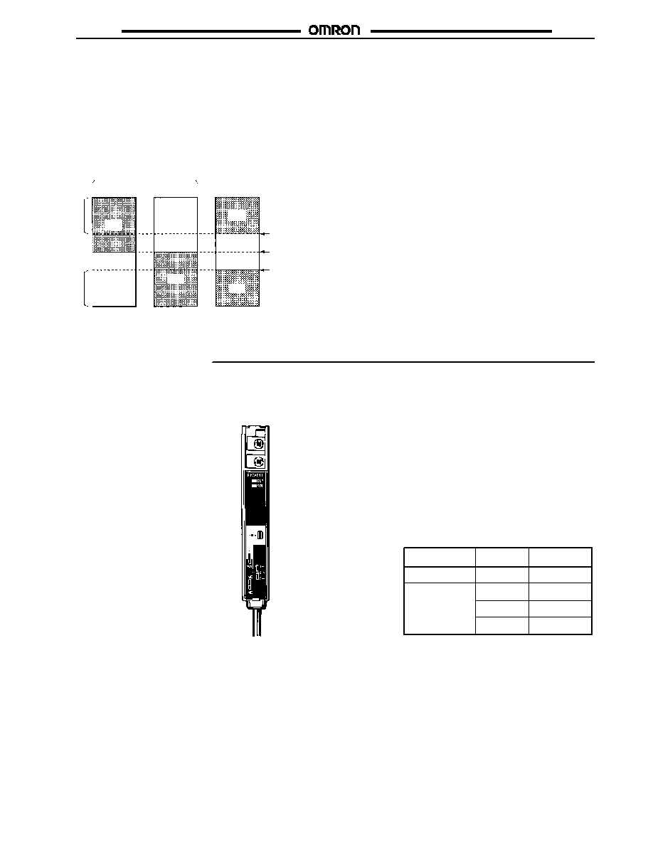
Nomenclature
J
SWITCHES AND FUNCTIONS
Operation Indicator
(Orange)
STB (Stability) Indicator (Green)
Also used for teaching monitor purposes.
Mode Selector
Operation Selector
Transistor output
(NPN open collector)
NC: Normally closed
NO: Normally open
Front side
Sensor Connection
Terminal (shielded ground)
Sensor Connection Terminal (conductor)
TEACH Button
Cable Length Selector
Cable Length Compensator
Set this switch according to the
cable length as shown in the table
below.
Cable (connector) side
Applicable
Sensor Head
Setting
Cable length
E2C-CR5B2
E2C-CR8A
E2C-CR8B
E2C-X1A
E2C-C1A
E2C-X1R5A
3 m
3 m
0 to 1 m
1 to 2 m
2 to 3 m
1 m
2 m
3 m
RUN: RUN mode is set.
T: Teaching mode is set, The output
transistor is turned OFF.

E2C-T
E2C-T
6
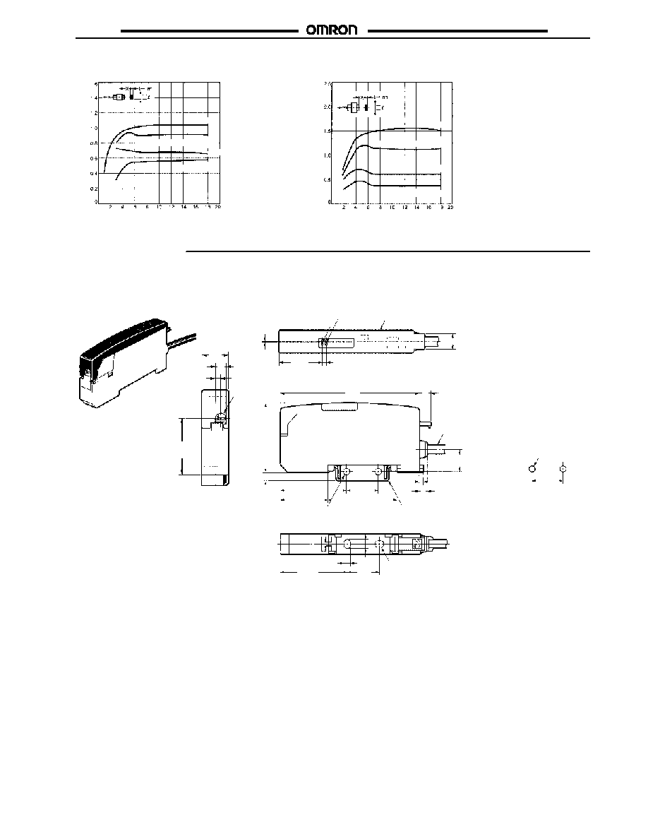
Engineering Data
J
OPERATING RANGE (TYPICAL)
E2C-CR8j
Se
n
s
i
n
g
d
i
s
t
a
n
c
e
X
(mm)
E2C-CR8j Sensing Head
Y (mm)
Target object:
iron 5 x 5 x 1 mm
Sensing distance
(variable): 0.16 to
0.8 mm
E2C-CR5B2
2-dia. Sensing Head
Y (mm)
E2C-X1A/-C1A
Se
n
s
i
n
g
d
i
s
t
a
n
c
e
X
(mm)
Y (mm)
Target object:
iron: 5 x 5 x 1 mm
Sensing distance
(variable): 0.2 to
1 mm
E2C-X1A Sensing Head
E2C-C1A Sensing Head
E2C-X1R5A
Se
n
s
i
n
g
d
i
s
t
a
n
c
e
X
(mm)
Y (mm)
Target object:
iron: 8 x 8 x 1 mm
Sensing distance
(variable): 0.3 to
1.5 mm
E2C-X1R5A
SensingHead
J
SENSING DISTANCE VS. TARGET OBJECT SIZE AND MATERIAL (TYPICAL)
Side of target object (mm)
Se
n
s
i
n
g
d
i
s
t
a
n
c
e
X
(mm)
E2C-CR8j
Se
n
s
i
n
g
d
i
s
t
a
n
c
e
X
(mm)
Side of target object (mm)
Iron
Iron
E2C-CR5B2
E2C-T
E2C-T
7
E2C-X1A/-C1A
Se
n
s
i
n
g
d
i
s
t
a
n
c
e
X
(mm)
E2C-X1R5A
Se
n
s
i
n
g
d
i
s
t
a
n
c
e
X
(mm)
Side of target object (mm)
Side of target object (mm)
Iron
Stainless steel (SUS304)
Brass
Aluminum
Iron
Stainless steel (SUS304)
Brass
Aluminum
Dimensions
Unit: mm (inch)
J
AMPLIFIER UNITS
E2C-T11
10
(0.39)
4
(0.16)
2
(0.08)
R2
OUT indicator
STB indicator
A (See Note.)
0.5
(0.02)
7
(0.28)
22.6
(0.89)
10.6
(0.42)
33.4
(1.31)
6
(0.24)
2.4
(0.09)
70
(2.76)
4.1
(0.16)
24
(0.94)
16
(0.63)
32.5
(1.28)
34.8
(1.37)
4
(0.16)
Vinyl-insulated round cable with 4 dia.,
three cores (0.12 dia. x 18)
Standard length: 2 m
Note: The mounting bracket can also be mounted to side A.
Mounting bracket (removable, provided
with the Proximity Sensor)
Two, 3.2-dia mounting holes
Mounting Holes
Two, M3
16
(0.63)
Two, mounting holes
33.4
(1.31)
16
(0.63)
3.4
(0.13)
4.4
(0.17)
21.6
(0.85)
2
(0.08)

E2C-T
E2C-T
8
E2C-T16
10
(0.39)
4
(0.16)
2
(0.08)
0.5
(0.02)
22.6
(0.89)
2
(0.08)
32.5
(1.28)
6
(0.24)
70
(2.76)
24
(0.94)
21.8
(0.86)
R2
5.5
(0.22)
36.7
(1.44)
OUT indicator
STB indicator
7
(0.28)
J
SENSOR HEADS
E2C-CR5B2
E2C-CR8A
E2C-CR8B
Note: 3.8-dia. coaxial cable is used for the E2C-CR8B.
2 dia.
3.5 dia.
1.2-dia shielded cable
Standard length: 3 m
2.5-dia. coaxial cable
Standard length: 3 m
15
(0.59)
15
(0.59)
E2C-X1A
2.5-dia. coaxial cable
Standard length: 3 m
15
(0.59)
18
(0.71)
8
(0.31)
4
(0.16)
E2C-X1R5A
E2C-C1A
2.5-dia. coaxial cable
Standard length: 3 m
2.5-dia. coaxial cable
Standard length: 3 m
13
(0.51)
15
(0.59)
18
(0.71)
18
(0.71)
4
(0.16)
5.4
(0.21)
3
(0.12)

E2C-T
E2C-T
9
Installation
J
AUTOMATIC TEACHING
The E2C-T is used for object detection, level difference detection, and positioning, and the sensitivity of the E2C-T must be set according
to the application. The following description provides information on the automatic teaching of the E2C-T for sensitivity adjustment.
Teaching Proximity Sensor with Separate Amplifier
1
Teaching with no
sensing target
(Used for normal
object detection)
2
Set the mode
selector to T.
Without sensing target
Press the TEACH button once.
Set the mode
selector to RUN.
ON point
The ON point is automatically adjusted in the
vicinity of the maximum stable sensing range.
T
RUN
(See Note 5.)
TEACH
T
RUN
Teaching with
and without
sensing target
(See Note 3.)
(Used for level
difference detec-
tion and plate
overlapping
detection)
Positioning
teaching
(See Note 4.)
(Used for detec-
tion of objects
too close to the
Sensor with ON
point specified)
1
2
3
1
2
3
4
Set the mode
selector to T.
Press the TEACH button once.
With lower-side level detected
With upper-side level detected
Press the TEACH button once. (2nd time)
Set the mode
selector to RUN.
The ON point is set in the
middle of the levels.
Be sure to take steps 1 and 2 in
numerical order.
Set the mode
selector to T.
Without target object
Press the TEACH button once.
With target object located in ON position
Press the TEACH button once. (2nd time)
With target object located in
the same position.
Set the mode
selector to RUN.
Press the TEACH button once. (3rd time)
The ON point is set to the teaching position.
Be sure to take steps 1 and 2 and 3
in numerical order.
ON point
T
RUN
(See Note 5.)
TEACH
TEACH
T
RUN
T
RUN
(See Note 5.)
TEACH
TEACH
TEACH
T
RUN
ON point
Note: 1. Refer to details in the Sensitivity Setting (Automatic Teaching) section of this data sheet.
2. Before use, be sure to perform the teaching of the E2C-T.
3. If a fine-difference teaching is performed, reset failures may result when the E2C-T is in operation even if the teaching is suc-
cessful. Make sure that the E2C-T resets smoothly after the teaching.
4. Be sure to perform positioning teaching within the stable sensing distance range, or reset failures may result -- even if teaching
is successful. Be sure to check that the E2C-T can be reset after teaching. Refer to Ratings for the stability sensing range.
5. No transistor output will be ON if the mode selector is set to T, and a wrong signal may be output. The utmost attention is re-
quired for positioning teaching.

E2C-T
E2C-T
10
Sensitivity Setting (Automatic Teaching) in Detail
Type of teaching
Procedure
Teaching without
a target object
1. Locate the Sensor Head in sensing distance range.
2. Set the mode selector to T.
3. Press the TEACH button once without a target object.
Wait for 1 s
Teaching is OK
Orange teaching indicator is ON.
4. Set the mode selector to RUN to complete the teaching operation.
:
Teaching is not OK
Orange teaching indicator flashes.
Check the connection of the sensor cable and make sure that there is no target object. Then repeat
steps 3 and 4.
Teaching with and
without a target
object
1. Locate the Sensor Head in sensing distance range.
2. Set the mode selector to T.
3. Move the target object to the position where the output should turn OFF. Then press the TEACH button once.
(First time)
Wait for 1 s
Teaching is OK
Orange teaching indicator is ON.
4. Move the target object to the position where the output should turn ON. Then press the TEACH button once.
(Second time)
Wait for 1 s
Teaching is OK
Orange indicator is ON, then the green indicator is ON.
5. Set the mode selector to RUN to complete the teaching operation.
:
Teaching is not OK
Orange teaching indicator flashes.
Check the connection of the sensor cable and change the position of the target object and the set
distance. Then repeat steps 3 through 5.
Positioning
teaching
1. Locate the Sensor Head in sensing distance range.
2. Set the mode selector to T.
3. Press the TEACH button once without a target object. (First time)
Wait for 1 s
Teaching is OK
Orange teaching indicator is ON.
4. Move the target object to the position where the output should turn ON. Then press the TEACH button once.
(Second time)
Wait for 1 s
Teaching is OK
Orange indicator is ON, then the green indicator is ON.
5. Press the teaching button once without changing the position of the target object. (Third time)
Wait for 1 s
Teaching is OK
Green indicator is ON, then both the orange and green
indicators are ON.
6. Set the mode selector to RUN to complete the teaching operation.
:
Teaching is not OK
Orange teaching indicator flashes.
Check the connection of the sensor cable and change the position of the target object and the set
distance. Then repeat steps 3 through 6.
Note: Be sure to perform the teaching of the E2C-T before use. Once the teaching of the E2C-T is performed, the teaching data set in
the E2C-T will be retained even after turning OFF the E2C-T.

E2C-T
E2C-T
11
Precautions
J
POWER SUPPLY VOLTAGE
Do not impose voltage exceeding the rated voltage range or
100 VAC on the E2C-T, to avoid damaging the E2C-T.
Load
Brown
Sensor
Black
Blue
J
LOAD SHORT-CIRCUITING
Do not short-circuit the load, or the E2C-T may be damaged.
The load short-circuit protection function is triggered provided
that power within the rated voltage range is supplied to the
E2C-T without a mistake in polarity.
Load
Brown
Sensor
(Load short-circuiting)
Black
Blue
J
MOUNTING
Do not tighten the nut of the E2C-j excessively. Tighten the nut
with a toothed washer to the following torque.
Part number
Torque
E2C-X1A
0.98 N S m (10 kgf S cm)
E2C-X1R5A
2.0 N S m (20 kgf S cm)
Note: The above applies to a nut used with a toothed washer.
J
INCORRECT WIRING
To avoid damaging the E2C-T, observe the correct polarity when
connecting the power supply and the load to the E2C-T.
Sensor
Load
Sensor
Load
Brown
Black
Blue
Brown
Blue
Black
If a set screw is used for mounting a screwless, column model,
make sure that the tightening torque does not exceed 0.2 N S m
(2 kgf S cm).
7 to 11.5 mm
Y92E-F3R5 Bracket
(3.5-dia. dedicated bracket
sold separately)
Y92E-F5R4 (5.4 dia.)
is sold separately.
M3 set screw end
Dimensions
Y92E-F3R5
Y92E-F5R4
3.3
(0.13)
0.4
(0.02)
4.2
(0.17)
5.3
(0.21)
0.4
(0.02)
5.6
(0.22)
3.2
(0.13)
21
(0.83)
4.2
(0.17)
10
(0.39)
13
(0.51)
22
(0.87)
3.2
(0.13)
10
(0.39)
4.2
(0.17)
14
(0.55)
E2C-T
E2C-T
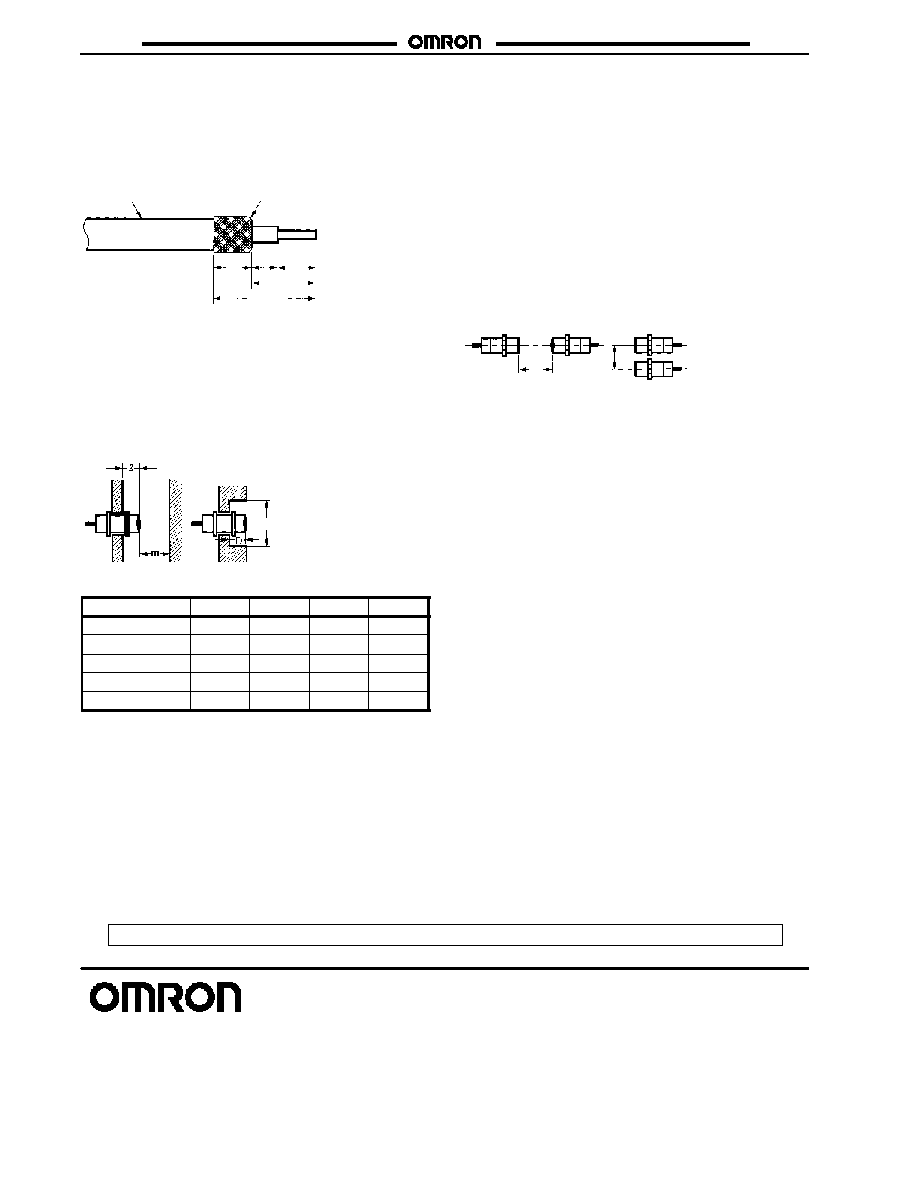
J
PROCESSING THE SENSOR CABLE
ENDS
Because of the Amplifier Unit's slim construction, the end of the
sensor cable connected to the E2C-j must be processed as
shown in the following illustration.
See Note 1.
See Note 2.
4 to 5
7 to 8
14 max.
Sensor cable
5
(0.20)
2.5
Note: 1. Be sure to turn over the braided shield, so that none of
its thin wires are left.
2. Make sure that the insulation distance of at least
2.5 mm is maintained.
J
INFLUENCE OF SURROUNDING METAL
If the Sensor is embedded, be sure to separate the Sensor from
surrounding metal objects, as shown in the following illustration.
d dia.
(mm)
Part number
d
D
m
E2C-CR5B2
2
6
2
1.5
E2C-CR8j
0
(3.5)
0
2.4
E2C-X1A
0
(5)
0
3
E2C-C1A
0
(5.4)
0
3
E2C-X1R5A
0
(8)
0
4.5
Note: Figures in parentheses indicate outer diameters of
shielded models.
Although the E2C-CR5B2 is a shielded model, this model
cannot be embedded in metal.
J
MUTUAL INTERFERENCE
If more than one Sensor is located face-to-face or in parallel, be
sure to maintain enough space, (as provided in the following
diagram), between adjacent Sensors, to suppress mutual
interference.
The mutual interference of the Sensors can be prevented by
cable length selector settings. However, the result is a change in
the coil characteristics of the Sensors, and the specified ratings
may not be satisfied in all permissible temperature or sensing
distance ranges. Test the operation of the Sensors before using
them in an actual application.
Note: The cable length of E2C-CR5B2 cannot be adjusted, so
mutual interference cannot be manipulated for this sensor
using cable length selector settings.
20
(0.79)
15
(0.59)
Cat. No. CEDSAX4 11/01 Specifications subject to change without notice. Printed in U.S.A .
OMRON ELECTRONICS LLC
One East Commerce Drive
Schaumburg, IL 60173
NOTE: DIMENSIONS SHOWN ARE IN MILLIMETERS. To convert millimeters to inches divide by 25.4.
1-800-55-OMRON
OMRON CANADA, INC.
885 Milner Avenue
Scarborough, Ontario M1B 5V8
416-286-6465
R
OMRON ON--LINE
Global -- http://www.omron.com
USA -- http://www.omron.com/oei
Canada -- http://www.omron.com/oci