 | –≠–ª–µ–∫—Ç—Ä–æ–Ω–Ω—ã–π –∫–æ–º–ø–æ–Ω–µ–Ω—Ç: E2CY-V3A | –°–∫–∞—á–∞—Ç—å:  PDF PDF  ZIP ZIP |
Document Outline
- First Page
- Ordering Information
- Specifications
- Operation
- Engineering Data
- Dimensions
- Nomenclature
- Installation
- Precautions
- Contacting Omron
R
Non-Ferrous Sensing Prox
E2CY
Non-Ferrous Detecting Proximity
Sensor with Separate, Teaching
Amplifier Features Simple Setup for
Accurate, Reliable Sensing
H
Detects only non-ferrous metals like
aluminum, copper and brass
H
Three teaching modes and one
automatic mode for easy setup
H
Three sensor heads to fit most
mounting requirements
H
Sensitivity can be easily monitored
using indicators on amplifier
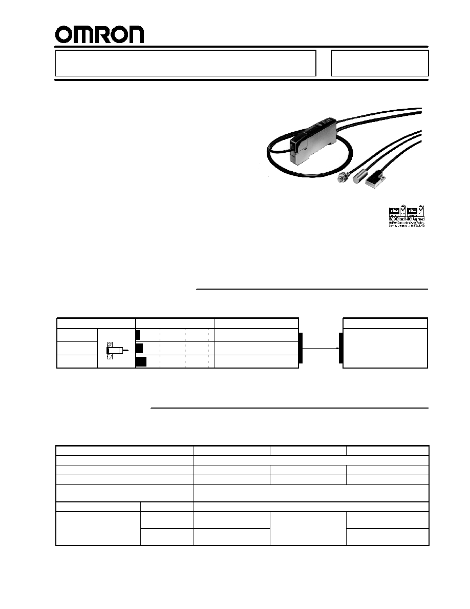
Ordering Information
Appearance
Stable sensing distance
Part number
M5
8 dia.
Flat model
Shielded
1.5 mm
2.0 mm
3.0 mm
E2CY-X1R5A
E2CY-C2A
E2CY-V3A
Part number
E2CY-T11
J
SENSOR HEADS
J
AMPLIFIER UNIT
Specifications
J
RATINGS/CHARACTERISTICS
Sensor Heads
Part number
E2CY-X1R5A
E2CY-C2A
E2CY-V3A
Target object
Non-ferrous metal
Standard target object
Aluminum: 8 x 8 x 1 mm
Aluminum: 8 x 8 x 1 mm
Aluminum: 12 x 12 x 1 mm
Stable sensing distance
0 to 1.5 mm
0 to 2.0 mm
0 to 3.0 mm
Response frequency
40 Hz min. (with Amplifier Unit fine-tuned), 100 Hz min. (with Amplifier Unit set to
NORM mode)
Ambient temperature
Operating
--10∞C to 55∞C (14∞F to 131∞F) with no icing
Influence of temperature on
sensing distance (at 23∞C)
--10∞C to 55∞C
(14∞F to 131∞F)
±15% max.
±10% max.
±15% max.
g
(
)
0∞C to 40∞C
(32∞F to 104∞F)
±10% max.
±10% max.
(This table continues on the next page.)

E2CY
E2CY
2
Specifications Table
-- continued from previous page
Part number
E2CY-X1R5A
E2CY-C2A
E2CY-V3A
Ambient humidity
Operating
35% to 95%
Vibration resistance
Destruction: 10 to 500 Hz, 2.0-mm double amplitude or 150 m/s
2
(approx. 15G)
for 2 hours each in X, Y, and Z directions
Shock resistance
Destruction: 500 m/s
2
(approx. 50G) three times each in X, Y, Z directions
Enclosure rating
IEC IP67
Connecting cable length
Coaxial cable with a standard length of 3 m for high-frequency use
Compensation range of cable length characteristic
0.5 to 5 m (See Note.)
Material
Case
Stainless steel
Zinc die-cast
Sensing surface
Heat-resistant ABS resin
Cable
Soft vinyl chloride
Weight (packaged state)
Approx. 35 g (with 3 m cord)
Accessories
M5 nut with toothed
washer
---
M2 screw, hexagonal nut,
spring washer, and flat
washer
Note: When extending the cable, use a 1.5D-2V (equivalent to JIS C 3501) cable with characteristic impedance of 50 .
Amplifier Unit
Supply voltage
12 to 24 VDC ± 10%, ripple (p-p): ±10% max.
Current consumption
40 mA max.
Sensing distance adjustment range
10% min. of stable sensing distance
Adjustment method
Teaching
Differential travel
10% max. of sensing distance in FINE mode.
15% max. of sensing distance in NORM mode.
Response time
Refer to the response frequency of the Sensor Head in use.
Control output
NPN open collector output of 100 mA max. with a max. residual voltage of 1 V
Self-diagnostic output
NPN open collector output of 100 mA max. with a max. residual voltage of 1 V
Circuit protection
Reverse polarity, surge voltage, and load short-circuit (for both control output and
diagnosis output)
Cable length
2 m, pull-out cable
Cable length compensation
Freely cut or extended within a range between 0.5 and 5 m
Indicators
Operation indicator (orange)
Excess gain level indicators (ON in green with sensing object in proximity and
ON in orange with no sensing object in proximity)
Fine-tuning indicator (green)
Ambient temperature
Operating
--10∞C to 55∞C (14∞F to 131∞F) with no icing
Ambient humidity
Operating
35 to 85%
Influence of temperature on sensing distance
(at 23∞C)
±10% max. --10∞C to 55∞C (14∞F to 131∞F)
Insulation resistance
50 M min. (at 500 VDC) between current carrying parts and case
Dielectric strength
1,000 VAC (50/60 Hz) for 1 min between current carrying parts and case
Vibration resistance
Destruction: 10 to 150 Hz, 1.5-mm double amplitude or 100 m/s
2
(approx. 10G)
for 2 hours each in X, Y, and Z directions
Shock resistance
Destruction: 300 m/s
2
(approx. 30G) for 3 hours each in X, Y, and Z directions
Degree of protection
IEC IP50 with the sensor cable and protective cover attached
Material
Case
PTB resin
Cover
Polycarbonate
Teaching monitor function
Orange and green indicators shared by operation and excess gain indication
Output status
Normally open or normally closed selectable
Weight (packaged state)
Approx. 75 g (with 2-m cable)
Accessories
Mounting brackets and instruction sheet

E2CY
E2CY
3
Operation
J
OUTPUT CIRCUIT
Self-diagnostic output:
100 mA max.
12 to 24 VDC
100 mA max.
0 V
39 V
Brown
Black
Blue
Orange
39 V
Main
circuit
Load
Control output
J
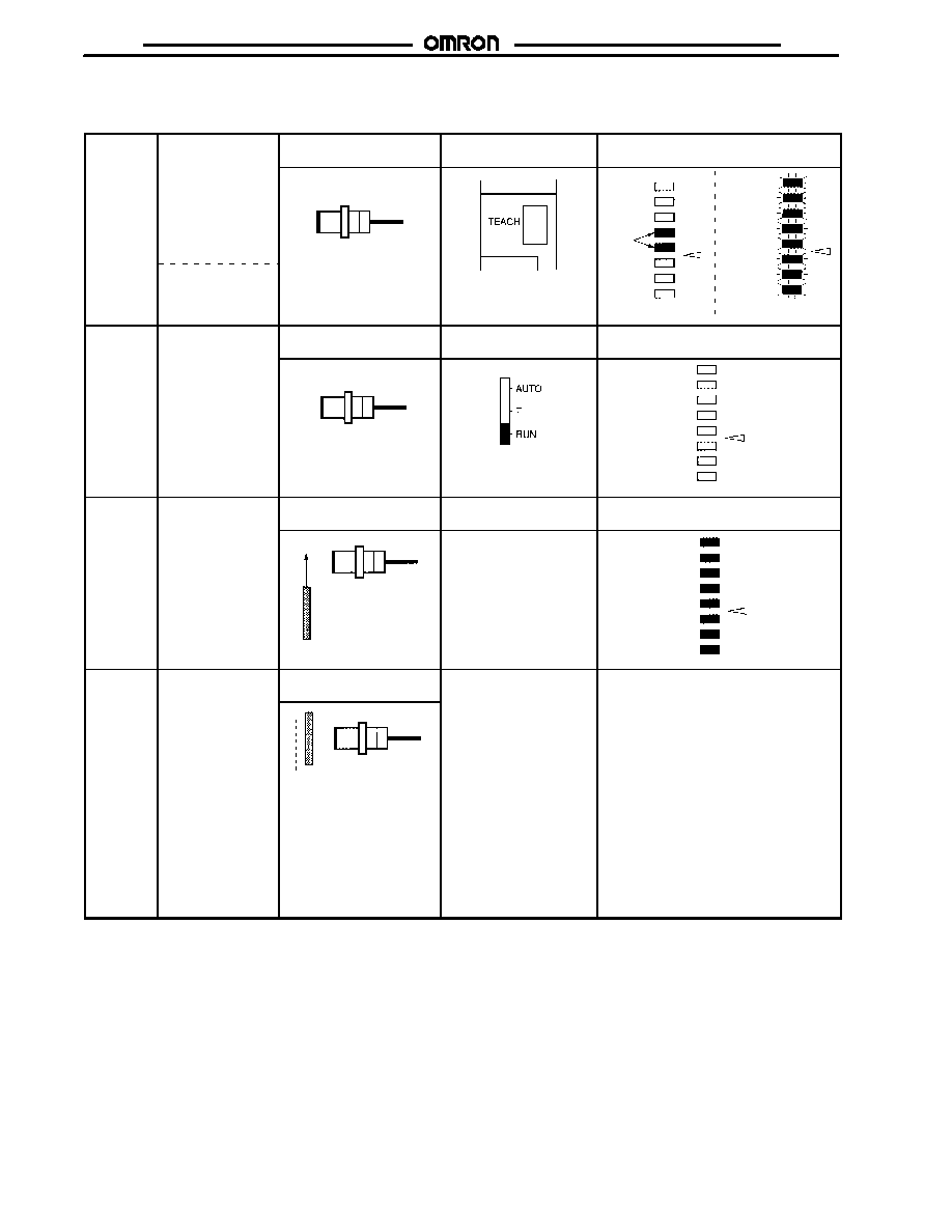
SENSITIVITY ADJUSTMENTS
Sensitivity adjustment is performed with or without a target object by setting the Sensor to the maximum sensing distance. The distance
can be set by using any of the following four methods.
Types of Sensing Adjustments and Applications
No.
Distance adjustment method
Application
Operation mode
selector
1
Teaching without sensing object
The E2CY is used as a normal proximity sensor.
T
2
Teaching with or without the sensing
object
∑
The E2CY is used for detecting the difference in target object level.
∑
The E2CY is used for discriminating types of target objects.
∑
The E2CY is used for discriminating the distance between the
sensing surface and target objects located within a certain range.
3
Positioning teaching
∑
Object positioning is required.
∑
The designation of sensor-ON point is required.
4
The distance is adjusted automatically
The E2CY is used as a normal proximity sensor.
AUTO
Note: All teaching methods can eliminate the influence of surrounding metal objects.
E2CY
E2CY
4
T Mode
Teaching Without Target Object
Step 1
Status of target object
Control panel
Indicators
(Excess gain level indicators)
Set the operation
mode selector to T.
Press the TEACH
button once with no
target object
located.
If all the indicators
flash, press the
TEACH button
again.
Sensor Head
No target object
TEACH button
Sensor
Head side
Sensor
Head side
ON
Flashing
OK
No good
Step 2
Status of target object
Control panel
Indicators
(Excess gain level indicators)
Set the operation
mode selector to
RUN.
Sensor Head
No target object
Operation mode selector
Sensor
Head side
OFF
Step 3
Status of target object
Control panel
Indicators
(Excess gain level indicators)
Move the target
object so that it
passes through the
sensing position
once.
Target
object
passing
Sensor Head
No switches are operated.
OFF after the
indicators are
ON for 1 s.
Sensor
Head side
OK
In
Operation
---
Sensitivity setting
position
---
---
p
ON
point
Target
object
Sensor Head
The ON point is set to a
distance that is approxi-
mately 1.2 times larger
than the distance between
the position where the
sample sensing object
passes and the sensing
surface of the Sensor
Head.
Note: After the E2CY is set to RUN mode, approximately 1.5 s will be required until the sensitivity is set from the moment the first target
object passes the sensing position. Therefore, move the next target object so that it passes through the sensing position 1.5 s after
the first target object passes the sensing position. Once the sensitivity adjustment is made, it will operate under the normal
response frequency.

E2CY
E2CY
5
Teaching With and Without Target Object (Level Difference Detection)
Step 1
Status of target object
Control panel
Indicators
(Excess gain level indicators)
Set the operation
mode selector to T.
Press the TEACH
button after locating
one of the sensing
levels in front of the
sensing surface.
Sensor Head
Sensing level
difference
TEACH button
Sensor
Head side
ON
OK
Step 2
Status of target object
Control panel
Indicators
(Excess gain level indicators)
Press the TEACH
button after locat-
ing the other sens-
ing level in front of
the sensing sur-
face.
If all the indicators
flash, repeat from
step 1. Or, change
the Sensor Head
position or set the
resolution selector
to FINE and then
repeat from step 1.
Sensor Head
Sensing level difference
TEACH button
Sensor
Head side
ON
OK
Sensor
Head side
Flashing
No good
Step 3
Sensitivity setting
position
Control panel
Indicators
(Excess gain level indicators)
Set the operation
mode selector to
RUN.
The ON point is set in the
middle of the two levels.
ON point
Sensor Head
Operation mode selector
OFF after the
indicators are
ON for 1 s.
Sensor
Head side
OK
Note: 1. The threshold level can be set to the same position by locating the target object at either one of the edges of the sensing range
when performing steps 1 and 2.
2. After setting the mode to RUN, confirm that all eight excess gain level indicators are ON.

E2CY
E2CY
6
Teaching With and Without Target Object (Located within Certain Range)
Step 1
Status of target object
Control panel
Indicators
(Excess gain level indicators)
Set the operation
mode selector to T.
Press the TEACH
button after locat-
ing the target
object at one edge
of the sensing
range.
Sensor Head
Sensing object at
a certain position
TEACH button
Sensor
Head side
ON
OK
Step 2
Status of target object
Control panel
Indicators
(Excess gain level indicators)
If all the indicators
flash, repeat from
step 1. Or, change
the Sensor Head
position or set the
resolution selector
to FINE and then
repeat from step 1.
Press the TEACH
button after locating
the other sensing
level in front of the
sensing surface.
Sensor Head
Sensing object at
a certain position
TEACH button
Sensor
Head side
Flashing
No good
Sensor
Head side
ON
OK
Step 3
Sensitivity setting
position
Control panel
Indicators
(Excess gain level indicators)
Set the operation
mode selector to
RUN.
Sensor Head
ON point
The ON point is located in
the middle of the edges.
Operation mode selector
OFF after the
indicators are
ON for 1 s.
Sensor
Head side
OK
Note: 1. The threshold level can be set to the same position by locating the target object at either one of the edges of the sensing range
when performing steps 1 and 2.
2. After setting the mode to RUN, confirm that all eight excess gain level indicators are ON.

E2CY
E2CY
7
Positioning Teaching
Step 1
Status of target object
Control panel
Indicators
(Excess gain level indicators)
Set the operation
mode selector to T.
Press the TEACH
button once with no
target object
located.
Sensor Head
No target object
TEACH button
Sensor
Head side
ON
OK
Step 2
Status of target object
Control panel
Indicators
(Excess gain level indicators)
Press the TEACH
button once after
locating the target
object at the
desired teaching
position.
If all the indicators
flash, repeat from
step 1.
Sensor Head
Target object at a
certain position
TEACH button
Sensor
Head side
Flashing
No good
Sensor
Head side
ON
OK
Step 3
Status of target object
Control panel
Indicators
(Excess gain level indicators)
Press the TEACH
button once with
the target object
located at the same
position.
If all the indicators
flash, repeat from
step 1.
Sensor Head
Target object at a
certain position
TEACH button
Sensor
Head side
ON
OK
Sensor
Head side
Flashing
No good
Step 4
Sensitivity setting
position
Control panel
Indicators
(Excess gain level indicators)
Set the operation
mode selector to
RUN.
Sensor Head
ON point
The ON-point is set at
the teaching position.
Operation mode selector
OFF after the
indicators are
ON for 1 s.
Sensor
Head side
OK
AUTO Mode
This mode is used for adjusting the target distance to its maximum without using any target object.
Set the operation mode selector
to AUTO with no target object
located at the sensing distance
Status of target object
Control panel
Indicators
(Excess gain level indicators)
g
j
located at the sensing distance.
The sensing distance is automatically
set to 80% to 110% of the stable
sensing distance of the E2CY.
Sensor Head
No target object
TEACH button
Sensor
Head side
Flashing
No good
OFF after the
indicators are
ON for 1 s.
Sensor
Head side
OK
Note: If the operation mode selector is set to AUTO when the E2CY is turned ON, the E2CY will make sensitivity adjustments automati-
cally. To maintain the sensitivity after adjustment, be sure to set the operation mode selector to RUN.

E2CY
E2CY
8
Engineering Data
J
OPERATING RANGE (TYPICAL)
E2CY-X1R5A
S
ens
i
n
g
d
i
s
tanc
e
X
(
mm)
Sensitivity
adjustment:
100%
Sensitivity
adjustment:
50%
Y (mm)
E2CY-C2A
Target object:
Aluminum 8 x 8 x 1 mm
Sensing distance (vari-
able): 0.15 to 1.5 mm
Y (mm)
E2CY-V3A
Y (mm)
Target object:
Aluminum 8 x 8 x 1 mm
Sensing distance (vari-
able): 0.2 to 2.0 mm
Sensitivity
adjustment:
100%
Sensitivity
adjustment:
50%
Target object:
Aluminum 12 x 12 x 1 mm
Sensing distance (variable):
0.3 to 3.0 mm
Sensitivity
adjustment:
100%
Sensitivity
adjustment:
50%
S
ens
i
n
g
d
i
s
tanc
e
X
(
mm)
S
e
ns
i
n
g
d
i
s
tanc
e
X
(
mm)

E2CY
E2CY
9
J
SENSING DISTANCE VS. SENSING OBJECT SIZE AND MATERIAL (TYPICAL)
E2CY-X1R5A
Aluminum,
brass, and
copper
Stainless
steel
(SUS304)
Target object size d (mm)
Aluminum,
brass, and
copper
Target object size d (mm)
E2CY-C2A
Stainless
steel
(SUS304)
S
e
ns
i
n
g
d
i
s
tanc
e
X
(
mm)
S
e
ns
i
n
g
d
i
s
tanc
e
X
(
mm)
Aluminum,
brass, and
copper
Target object size d (mm
)
E2CY-V3A
Stainless
steel
(SUS304)
Se
n
s
in
g
d
ist
a
n
c
e
X
(
m
m
)
J
TEMPERATURE INFLUENCE (TYPICAL)
E2CY-C2A
Ambient temperature (∞C)
Ambient temperature (∞C)
Sensitivity
adjustment:
100%
Sensitivity
adjustment:
120%
Sensitivity
adjustment:
120%
Sensitivity
adjustment:
100%
E2CY-X1R5A
S
ens
i
n
g
d
i
s
tanc
e
X
(
mm)
S
ens
i
n
g
d
i
s
tanc
e
X
(
mm)

E2CY
E2CY
10
E2CY-V3A
Ambient temperature (∞C)
Sensitivity
adjustment:
120%
Sensitivity
adjustment:
100%
S
ens
i
n
g
d
i
s
tanc
e
X
(
mm)
Dimensions
Unit: mm (inch)
J
SENSOR HEADS
E2CY-X1R5A
Vinyl-insulated round coaxial cable with
2.5 dia. (28/0.08) with a single conductor
Standard length: 3 m
E2CY-C2A
Vinyl-insulated round coaxial cable with
2.5 dia. (28/0.08) with a single conductor
Standard length: 3 m
E2CY-V3A
Mounting Holes
Vinyl-insulated round coaxial cable with
2.5 dia. (28/0.08) with a single conductor
Standard length: 3 m
Sensing face Two, mounting
holes
Two, M2
Two, nuts
Two, toothed washers
18
(0.71)
15
(0.59)
4
(0.16)
25
(0.98)
23
(0.91)
5.2
(0.20)
10.7
(0.42)
4.8
(0.19)
4.9
(0.19) 2.4
(0.09)
3.7
(0.15)
12
(0.47)
2
(0.08)
4.6
(0.18)
4.5
(0.18)
18
(0.71)
4.8
(0.19)
8
(0.31)
8
(0.31)

E2CY
E2CY
11
J
AMPLIFIER UNIT
E2CY-T11
Excess gain level indicator
Operation indicator
Fine-tuning indicator
Mounting bracket
Vinyl-insulated round coaxial cable with
4 dia. (18/0.12) with four conductors
Standard length: 2 m
Two, 3.2-dia. mounting holes
Two, mounting holes
Note: Sensor mounting screws, M2.6
0.5
(0.02)
10
(0.39)
4
(0.16)
2
(0.08)
21.6
(0.85)
4.1
(0.16)
22.2
(0.87)
24.6
(0.97)
15.5
(0.61)
6
(0.24)
70
(2.76)
10.6
(0.42)
2.4
(0.09)
16
(0.63)
33.4
(1.31)
7
(0.28)
24
(0.94)
34.8
(1.37)
4
(0.16)
32.5
(1.28)
0.2
(0.01)
3.4
(0.13)
4.4
(0.17)
33.4
(1.31)
16
(0.63)
10.5
(0.41)
Two, M3
16
(0.63)
Mounting Holes
Nomenclature
J
CONTROL PANEL OF AMPLIFIER UNIT
Sensor Head mounting side
Operation indicator (orange)
Fine-tuning indicator (green)
Resolution selector
Output mode selector
Cable extension side
Excess gain level
indicators (green)
Excess gain level
indicators (orange)
Operation mode selector
Sensor mounting
screw (M2.6)
TEACH button
Operation Mode Selector
AUTO Mode: The sensitivity is automatically adjusted within
a range of approximately 80% to 110% of the
rated sensing distance.
T Mode:
This mode is used when adjusting the
sensitivity of the Sensor. (The output transistor
does not operate in this mode.)
RUN Mode: This mode is used for the normal operation of
the Sensor.
Resolution Selector
If the E2CY often has a teaching error when detecting
fine-tuning differences, set the resolution selector to FINE.
The response speed will drop but improvement in the
sensing accuracy of the E2CY can be expected.
Output Mode Selector
Used to select the transistor mode (NPN open collector output).
NO: Normally open output
(Output transistor will turn ON if a sensing object is
present.)
NC: Normally closed output
(Output transistor will turn ON if a sensing object is
not present.)
J
SELF-DIAGNOSTIC FUNCTION
The output transistor of self-diagnostic output will turn ON in the following cases.
1. Sensor cable disconnection
The self-diagnostic output will turn ON approximately 105 ms after the sensor cable disconnects.
2. Sensor cable short-circuit
The self-diagnostic output will turn ON approximately 105 ms after the sensor cable short-circuits.
3. Control output short-circuiting
The self-diagnostic output will turn ON if excessive current flows to the load due to load wire short-circuiting.
4. Internal memory error
When the E2CY is turned ON in RUN or TEACH mode, the self-diagnostic output will turn ON if the teaching status of the E2CY is not
stored properly in the internal memory.
E2CY
E2CY
12
J
INDICATORS
Operation Indicator (Orange)
The operating indicator will turn ON when the control output is ON.
Excess Gain Level Indicators (Green and Orange)
The excess gain level indicators will be ON according to the distance of the target object as shown below.
OFF
ON
Threshold level
Short distance
Long distance
Note: 1. All indicators will be ON if the target object is at a position of approximately 80% of the preset sensing distance.
2. All indicators will be OFF at a position of approximately 110% of the preset sensing distance.
(See Note 1.)
(See Note 2.)
Green
Orange
Position of
target
objects
<Excess Gain Level>
Installation
J
CONNECTION
Sensor Head
Shielded wire
Conductor
Amplifier Unit
Control output
Self-diagnostic
output
Connection of Sensor Head and Amplifier Unit
Brown
Black
Blue
Orange
12 to 24 VDC
0 V

E2CY
E2CY
13
Precautions
J
AVOID DAMAGE TO THE E2CY
Power Supply Voltage
Do not impose voltage exceeding the rated voltage range or
100 VAC on the E2CY.
Load
Brown
Sensor
Black
Blue
Load Short-circuit
Do not short-circuit the load.
The load short-circuit protection function is triggered provided
that power within the rated voltage range is supplied to the E2CY
without a mistake in polarity.
Load
Brown
Sensor
(Load short-circuiting)
Black
Blue
Incorrect Wiring
Be sure to observe correct polarity when connecting the power
supply and load to the E2CY.
Sensor
Load
Sensor
Load
Brown
Blue
Black
Brown
Black
Blue

E2CY
E2CY
14
J
SELF-DIAGNOSTIC OUTPUT AND INDICATORS
If one of the following errors result, the user can find the errors using the self-diagnostic output and indicators of the E2CY. If the self-diagnostic
output line is short-circuited, however, self-diagnostic output will not be available.
Error
indication
Flashing
Flashing
Flashing
Flashing
Flashing
Flashing
Flashing
Flashing
Cause of
error
∑
The Sensor Head cable is
disconnected.
∑
The Sensor Head cable is
short-circuited.
∑
The Sensor Head is not
connected properly.
∑
The load is short-
circuited.
∑
The self-diagnostic
output line is short-
circuited.
∑
Proper teaching has not
completed.
∑
The internal memory
element is broken.
Remedy
∑
Make sure that the Sensor
Head is connected
properly.
∑
If there is a Sensor Head
cable disconnection, repair
the disconnected cable
portion or replace the
Sensor Head.
Note: A similar problem will
occur if ferrous metal,
such as iron, is located
close to the E2CY.
∑
Correctly connect the
load to the control
output.
∑
Correctly connect the
self-diagnostic output
line.
∑
Perform the teaching
operation of the E2CY
again.
∑
Replace the E2CY
amplifier.
J
TIGHTENING TORQUE
Do not tighten the nut of the E2CY-j excessively. Be sure to
tighten the nut with a toothed washer to the following torque.
Model
Torque
E2CY-X1R5A
1.0 N S m (10 kgf S cm)
Note: The above applies to a nut used with a toothed washer.
If a set screw is used for mounting a screwless, column model,
make sure that the tightening torque does not exceed 0.2 N S m
(2 kgf S cm).
M3 set screw end
7 to 11.5 mm
J
INFLUENCE OF SURROUNDING METAL
If the Sensor is embedded, be sure to separate the Sensor from
surrounding metal objects as shown in the following illustration.
d dia.
Model
Distance (mm)
d
D
m
E2CY-X1R5A
0
5
0
9
E2CY-C2A
0
8
0
15
E2CY-V3A
0
12
0
18
The E2CY-V3A can be embedded in metal with the sensing
surface at the same level as the metal surface.
E2CY-V3A

E2CY
E2CY
15
J
MUTUAL INTERFERENCE
If more than one Sensor is positioned face-to-face or in parallel,
be sure to maintain enough space, as provided in the following
table, between adjacent Sensors to suppress mutual
interference.
Model
Distance (mm)
A
B
E2CY-X1R5A
20
15
E2CY-C2A
20
15
E2CY-V3A
30
12
J
AMPLIFIER UNIT MOUNTING AND
REMOVAL
Mounting
1. Place the front part of the Amplifier Unit on the mounting
bracket provided with the E2CY or the DIN track so that the
front part will engage with the mounting bracket or DIN track.
2. Press the rear part of the Amplifier Unit onto the mounting
bracket or DIN track.
(1)
(2)
Front part
Rear part
Fixture rail (yellow)
DIN track (or mounting bracket)
If the Amplifier Unit is side-mounted to the bracket provided,
secure it using M3 screws with flat washers (6 mm in dia., or
less).
Flat washers (6 dia. max. each)
Removal
Press the Amplifier Unit in the direction shown by arrow (3) in the
following illustration and lift up the fiber insertion part of the
Amplifier Unit in the direction shown by arrow (4), so the Amplifier
Unit can be removed easily. No screwdriver is required to remove
the Amplifier Unit.
DIN track
(3)
(4)
J
TEACHING
Make sure that the Sensor is in operating condition before
making sensitivity adjustments.
J
PROCESSING THE SENSOR CABLE
ENDS
When cutting or extending the cable, the end of the sensor cable
connected to the E2CY-j must be processed as shown in the
following illustration.
4 to 5
7 to 8
14 max.
*2
*1
Sensor cable
Note:*1. Be sure to turn over the braided shield so that none of
its thin wires are left.
*2. Make sure that a minimum of 2.5 mm of cable
insulation is maintained.
J
POWER ON OPERATION
∑
The E2CY will be ready for sensing within 50 ms after the
power is turned ON.
∑
When the E2CY and load are connected to different power
supplies, you must turn ON the power supply to the E2CY
first.
J
EFFECT OF HIGH-FREQUENCY
ELECTRO-MAGNETIC FIELD
If the E2CY is located near a high-frequency generation unit or
transceiver, it may be affected by such a unit and result in
malfunction.

E2CY
E2CY
Cat. No. CEDSAX4 11/01 Specifications subject to change without notice. Printed in U.S.A.
OMRON ELECTRONICS LLC
One East Commerce Drive
Schaumburg, IL 60173
NOTE: DIMENSIONS SHOWN ARE IN MILLIMETERS. To convert millimeters to inches divide by 25.4.
1-800-55-OMRON
OMRON CANADA, INC.
885 Milner Avenue
Scarborough, Ontario M1B 5V8
416-286-6465
R
OMRON ON--LINE
Global -- http://www.omron.com
USA -- http://www.omron.com/oei
Canada -- http://www.omron.com/oci