R
2
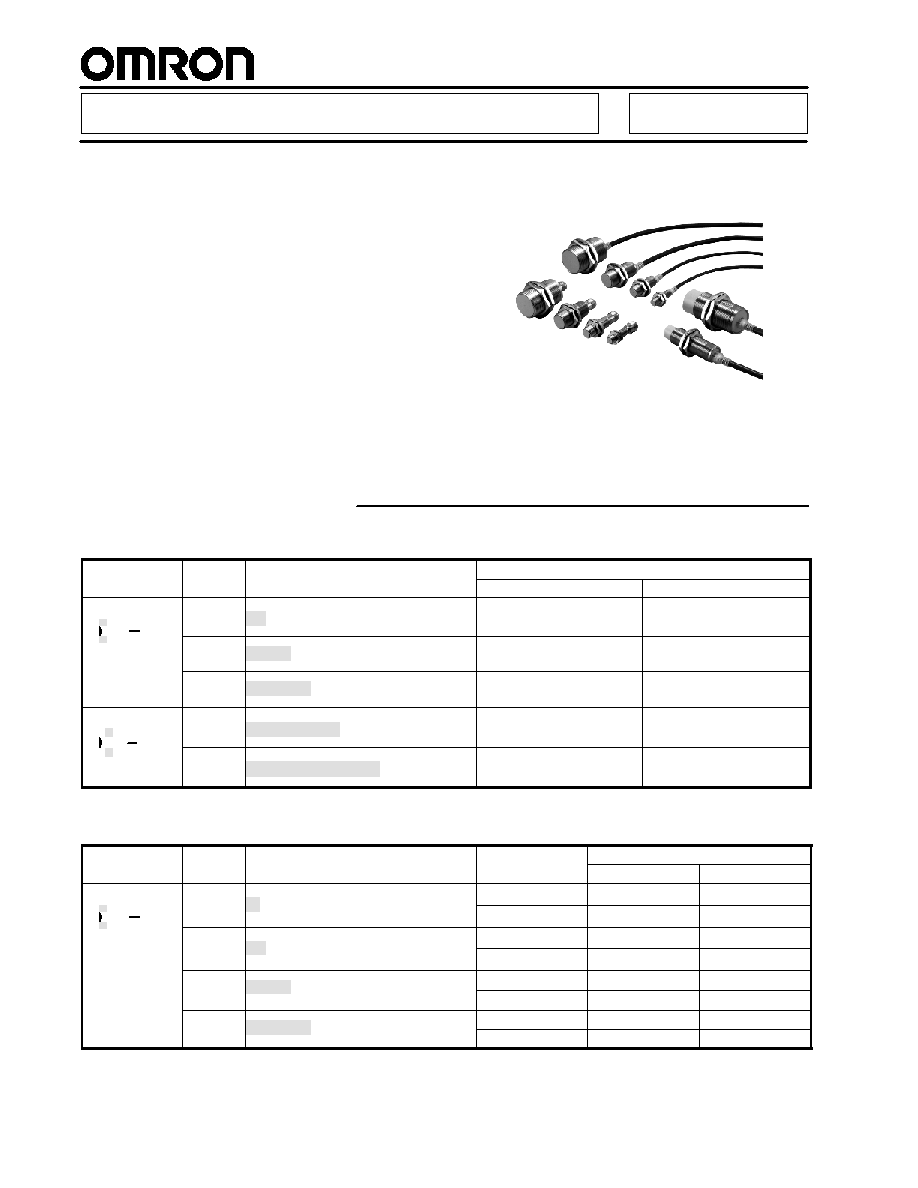
Extended Range Inductive Prox
E2EM
Greater Sensing Distance Offers
Greater Design Flexibility
H
Sensing distances approximately 1.5 to
2 times larger than that of any
conventional Sensor
H
Reduces problems such as the collision
of workpieces
H
The E2EM has no polarity, thus
eliminating problems associated with
reversed wiring
Ordering Information
J
DC 2-WIRE/PRE-WIRED MODELS
Type
Size
Sensing distance
Part number
Type
Size
Sensing distance
NO
NC
Shielded
M12
4 mm
E2EM-X4X1
E2EM-X4X2
M18
8 mm
E2EM-X8X1
E2EM-X8X2
M30
15 mm
E2EM-X15X1
E2EM-X15X2
Unshielded
M18
16 mm
E2EM-X16MX1
E2EM-X16MX2
M30
30 mm
E2EM-X30MX1
E2EM-X30MX2
J
DC 3-WIRE/PRE-WIRED MODELS
Type
Size
Sensing distance
Output
Part number
Type
Size
Sensing distance
Output
Configuration
NO
NC
Shielded
M8
2 mm
NPN
E2EM-X2C1
E2EM-X2C2
2 mm
PNP
E2EM-X2B1
E2EM-X2B2
M12
4 mm
NPN
E2EM-X4C1
E2EM-X4C2
4 mm
PNP
E2EM-X4B1
E2EM-X4B2
M18
8 mm
NPN
E2EM-X8C1
E2EM-X8C2
8 mm
PNP
E2EM-X8B1
E2EM-X8B2
M30
15 mm
NPN
E2EM-X15C1
E2EM-X15C2
M30
15 mm
PNP
E2EM-X15B1
E2EM-X15B2
E2EM
E2EM
3
J
DC 3-WIRE/CONNECTOR MODELS
Type
Size
Sensing distance
Output
Part number
Type
Size
Sensing distance
Output
Configuration
NO
NC
Shielded
M8
2 mm
NPN
E2EM-X2C1-M1
E2EM-X2C2-M1
2 mm
PNP
E2EM-X2B1-M1
E2EM-X2B2-M1
M12
4 mm
NPN
E2EM-X4C1-M1
E2EM-X4C2-M1
4 mm
PNP
E2EM-X4B1-M1
E2EM-X4B2-M1
M18
8 mm
NPN
E2EM-X8C1-M1
E2EM-X8C2-M1
8 mm
PNP
E2EM-X8B1-M1
E2EM-X8B2-M1
M30
15 mm
NPN
E2EM-X15C1-M1
E2EM-X15C2-M1
M30
15 mm
PNP
E2EM-X15B1-M1
E2EM-X15B2-M1
J
ACCESSORIES (ORDER SEPARATELY)
Mounting Brackets
Four kinds of resin mounting brackets are available. Choose an appropriate one depending on external dimensions
Description
Part number
Mounting brackets
Fits M8 size sensors
Y92E-B8
Mounting brackets
Fits M12 size sensors
Y92E-B12
Fits M18 size sensors
Y92E-B18
Fits M30 size sensors
Y92E-B30
Note: When using the Mounting Brackets for unshielded models, pay attention to the influence of surrounding metals. (For dimensions of
Sensors, refer to the dimensions shown for each model.)

E2EM
E2EM
4
Specifications
J
RATINGS/CHARACTERISTICS
E2EM-XjXj DC 2-wire Models
Part number
E2EM-X4Xj
E2EM-X8Xj
E2EM-X16MXj
E2EM-X15Xj
E2EM-X30MXj
Size
M12
M18
M30
Type
Shielded
Shielded
Unshielded
Shielded
Unshielded
Sensing distance
4 mm (0.16 in.)
�10%
8 mm (0.31 in.)
�10%
16 mm (0.63 in.)
�10%
15 mm (0.59 in.)
�10%
30 mm (1.18 in.)
�10%
Supply voltage (operating
voltage)
12 to 24 VDC, ripple (p-p): 10% max., (10 to 30 VDC)
Leakage current
0.8 mA max.
Sensing object
Ferrous metal (refer to Engineering Data for non-ferrous metal)
Setting distance
0 to 3.2 mm
(0.13 in.)
0 to 6.4 mm
(0.25 in.)
0 to 12.8 mm
(0.50 in.)
0 to 12 mm
(0.47 in.)
0 to 24 mm
(0.94 in.)
Standard object (mild steel)
12 x 12 x 1 mm
(0.47 x 0.47 x
0.04 in.)
18 x 18 x 1 mm
(0.71 x 0.71 x
0.04 in.)
45 x 45 x 1 mm
(1.77 x 1.77 x
0.04 in.)
30 x 30 x 1 mm
(1.18 x 1.18 x
0.04 in.)
70 x 70 x 1 mm
(2.76 x 2.76 x
0.04 in.)
Differential travel
15% max. of sensing distance
Response frequency
1 kHz
0.5 kHz
0.4 kHz
0.25 kHz
0.1 kHz
Operation (with sensing object
approaching)
X1 models:
NO
X2 models:
NC
Control output (Switching
capacity)
5 to 100 mA
Circuit protection
Surge absorber, load short-circuit protection
Indicator
X1 models:
Operation indicator (red LED), operation set indicator (green LED)
X2 models:
Operation indicator (red LED)
Ambient temperature
Operating: --25�C to 70�C (--13� to 158�F) with no icing or condensation
Storage: --40�C to 85�C (--40� to 185�F) with no icing or condensation
Ambient humidity
Operating/Storage: 35% to 95% (with no condensation)
Temperature influence
�15% max. of sensing distance at 23�C (73.4�F) in temp. range of --25�C to 70�C (--13� to 158�F)
Voltage influence
�1% max. of sensing distance in rated voltage range �15%
Residual voltage
5 V max. under load current of 100 mA with cable length of 2 m (78.7 in.)
Insulation resistance
50 M min. (at 500 VDC) between current carry parts and case
Dielectric strength
1,000 VAC at 50/60 Hz for 1 min between current carry parts and case
Vibration resistance
10 to 55 Hz, 1.5-mm (0.06 in.) double amplitude for 2 hours each in X, Y, and Z directions
Shock resistance
1,000 m/s
2
for (3280.8 ft/s
2
) 10 times each in X, Y, and Z directions
Degree of protection
IEC60529 IP67
Connection method
Pre-wired models standard length: 2 m (78.7 in.)
Weight (packaged)
Approx. 60 g
(0.13 lbs)
Approx. 130 g
(0.28 lbs)
Approx. 150 g
(0.33 lbs)
Approx. 180 g
(0.39 lbs)
Approx. 210 g
(0.46 lbs)
Material
Case
Brass
Material
Sensing
surface
PBT

E2EM
E2EM
5
E2EM-XjBj/Cj DC 3-wire Models
Part number
E2EM-X2Bj/Cj
E2EM-X4Bj/Cj
E2EM-X8Bj/Cj
E2EM-X15Bj/Cj
Size
M8
M12
M18
M30
Type
Shielded
Sensing distance
2 mm (0.08 in) �10%
4 mm (0.16 in) �10%
8 mm (0.31 in) �10%
15 mm (0.59 in) �10%
Supply voltage (operating voltage
range) (see note 1)
12 to 24 VDC, ripple (p-p): 10% max., (10 to 40 VDC)
Leakage current
13 mA max.
Sensing object
Ferrous metal (refer to Engineering Data for non-ferrous metal)
Setting distance
0 to 1.6 mm
(0 to 0.06 in)
0 to 3.2 mm
(0 to 0.13 in)
0 to 6.4 mm
(0 to o.25 in)
0 to 12 mm
(0 to 0.47 in)
Standard object (mild steel)
8 x 8 x 1 mm
(0.31 x 0.31 x 0.04 in)
12 x 12 x 1 mm
(0.47 x 0.47 x 0.04 in)
18 x 18 x 1 mm
(0.71 x 0.71 x 0.04 in)
30 x 30 x 1 mm
(1.18 x 1.18 x 0.04 in)
Differential travel
10% max. of sensing distance
Response frequency (see note 2)
1.5 kHz
0.5 kHz
0.3 kHz
0.1 kHz
Operation (with sensing object
approaching)
B1, C1 models:
NO
B2, C2 models:
NC
Control output Switching capacity
(see note 1)
200 mA max.
Circuit protection
Reverse connection protection, surge absorber, load short-circuit protection
Indicator
Operation indicator (Yellow LED)
Ambient temperature (see note 2)
Operating/Storage: --40�C to 85�C (--40� to 185�F) with no icing or
condensation
Operating:
--25�C to 70�C
(--13� to 158�F)
Storage:
--40�C to 85�C
(--40� to 185�F)
(with no icing or
condensation)
Ambient humidity
Operating/Storage: 35% to 95% (with no condensation)
Temperature influence
�15% max. of sensing distance at 23�C (73.4�F) within temperature
range of --40�C to 85�C (--40� to 185�F)
�10% max. of sensing distance at 23�C (73.4�F) within temperature
range of --25�C to 70�C (--13� to 158�F)
�15% max. of sensing
distance at 23�C
(73.4�F) within
temperature range of
--25�C to 70�C
(--13� to 158�F)
Voltage influence
�1% max. of sensing distance in rated voltage range �15%
Residual voltage
2 V max. under load current of 200 mA with cable length of 2 m (78.7 in)
Insulation resistance
50 M min. (at 500 VDC) between current carry parts and case
Dielectric strength
1,000 VAC at 50/60 Hz for 1 min between current carry parts and case
Vibration resistance
10 to 55 Hz, 1.5-mm (0.06 in) double amplitude for 2 hours each in X, Y, and Z directions
Shock resistance
500 m/s
2
(1640
ft/s
2
)for 10 times each
in X, Y, and Z
directions
1,000 m/s
2
(3280 ft/s
2
) for 10 times each in X, Y, and Z directions
Degree of protection
IEC60529 IP67
Connection method
Pre-wired models standard length: 2 m (78.7 in)
Connector models ("-M1" models)
Weight
(packaged)
Pre-wired
Approx. 55 g (0.12 lbs)
Approx. 65 g (0.14 lbs)
Approx. 140 g
(0.31 lbs)
Approx. 190 g
(0.42 lbs.)
(p
g )
Connector
Approx. 10 g (0.02 lbs.)
Approx. 20 g (0.04 lbs.)
Approx. 40 g (0.09 lbs.)
Approx. 90 g (0.20 lbs.)
Material
Case
Stainless steel
(SUS303)
Brass
Sensing surface
PBT
Note: 1. When using the M8 models within the temperature range from 70�C to 85�C, (158� to 185�F) the voltage range must be from 10
to 30 VDC and control output (switching capacity) must be 100 mA max.
2. The response frequency of the DC switch section is an average value.
E2EM
E2EM
6
Engineering Data
J
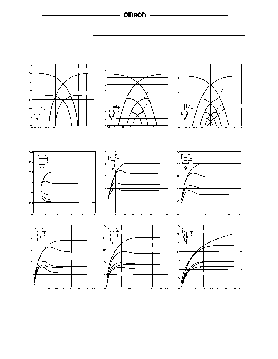
OPERATING RANGE (TYPICAL)
E2EM-X4B/C
Unshielded Models
E2EM-XjMXj
Sensing distance Y (mm)
Shielded Models
E2EM-XjXj
E2EM-XBj/Cj
Sensing distance Y (mm)
Sensing distance Y (mm)
Se
n
s
i
n
g
d
i
s
t
a
n
c
e
X
(mm)
Se
n
s
i
n
g
d
i
s
t
a
n
c
e
X
(mm)
Se
n
s
i
n
g
d
i
s
t
a
n
c
e
X
(mm)
E2EM-X30MX
E2EM-X16MX
E2EM-X15X
E2EM-X8X
E2EM-X4X
E2EM-X15B/C
E2EM-X8B/C
E2EM-X2B/C
J
INFLUENCE OF SENSING OBJECT SIZE AND MATERIALS
Brass
Copper
Brass
Brass
Brass
Copper
Stainless
steel
(SUS304)
Brass
E2EM-X2jj
E2EM-X4jj
E2EM-X8jj
Mild steel
Stainless
steel
(SUS304)
Copper
Brass
Aluminum
t = 1 mm
Side length of sensing object d (mm)
Mild steel
Stainless
steel
(SUS304)
t = 1 mm
Side length of sensing object d (mm)
Mild steel
t = 1 mm
Side length of sensing object d (mm)
E2EM-X15jj
E2EM-X16MXj
E2EM-X30MXj
Mild steel
Stainless steel
(SUS304)
Copper
t = 1 mm
Mild steel
Stainless steel
(SUS304)
t = 1 mm
Mild steel
Stainless steel
(SUS304)
Aluminum
t = 1 mm
Aluminum
Side length of sensing object d (mm)
Side length of sensing object d (mm)
Side length of sensing object d (mm)
Aluminum
Copper
Copper
Se
n
s
i
n
g
d
i
s
t
a
n
c
e
X
(mm)
Se
n
s
i
n
g
d
i
s
t
a
n
c
e
X
(mm)
Se
n
s
i
n
g
d
i
s
t
a
n
c
e
X
(mm)
Se
n
s
i
n
g
d
i
s
t
a
n
c
e
X
(mm)
Se
n
s
i
n
g
d
i
s
t
a
n
c
e
X
(mm)
Se
n
s
i
n
g
d
i
s
t
a
n
c
e
X
(mm)
d�d
d�d
d�d
d�d
d�d
d�d
E2EM
E2EM
7
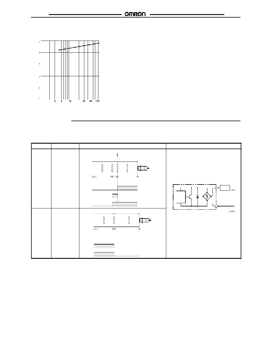
J
RESIDUAL VOLTAGE CHARACTERISTICS
E2EM-XjXj
O
u
t
put
r
e
s
i
dual
v
o
lt
age
(
V
)
Load current (mA)
Operation
J
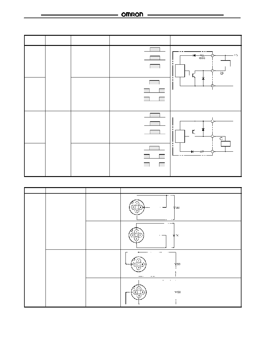
OUTPUT CIRCUITS
E2EM-XjXj DC 2-wire Models
Operation
Model
Timing chart
Output circuit
NO
E2EM-X4X1
E2EM-X8X1
E2EM-X15X1
E2EM-X16MX1
E2EM-X30MX1
Non-sensing
zone
Unstable
sensing zone
Setting
position
Stable sensing
zone
Sensing
object
Proximity
Sensor
Ra
t
e
d
s
e
n
s
in
g
di
s
t
anc
e
ON
OFF
Set indicator
(green)
ON
OFF
Operation
indicator
(red)
Control
output
ON
OFF
Main
circuit
(0 V)
0 V
Brown
Blue
Load
NC
E2EM-X4X2
E2EM-X8X2
E2EM-X15X2
E2EM-X16MX2
E2EM-X30MX2
Ra
t
e
d
s
e
n
s
in
g
di
s
t
anc
e
Non-sensing zone
Sensing zone
Proximity
Sensor
ON
OFF
Control
output
Sensing
object
Operation
indicator
(red)
ON
OFF
0 V
Note: 1. The load can be connected to
either +V or 0 V line.
2. There is no polarity.
E2EM
E2EM
8
E2EM-XjBj/Cj(-M1) DC 3-wire Models
Operation
Output speci-
fications
Model
Timing chart
Output circuit
NO
NPN open
collector
output
E2EM-X2C1 (-M1)
E2EM-X4C1 (-M1)
E2EM-X8C1 (-M1)
E2EM-X15C1 (-M1)
Sensing object
Control output
Yes
No
ON
OFF
Operation indicator
(yellow)
ON
OFF
Main
circuit
Brown
Black
or
Load
NC
E2EM-X2C2
E2EM-X4C2
E2EM-X8C2
E2EM-X15C2
Sensing object
Control output
Yes
No
ON
OFF
ON
OFF
Operation indicator
(yellow)
Blue
Note: Pin 4 is NO and Pin 2 is NC.
0 V
NO
PNP open
collector
output
E2EM-X2B1 (-M1)
E2EM-X4B1 (-M1)
E2EM-X8B1 (-M1)
E2EM-X15B1 (-M1)
Sensing object
Control output
Yes
No
ON
OFF
Operation indicator
(yellow)
ON
OFF
Main
circuit
Brown
Black
or
Load
1
4
2
+V
NC
E2EM-X2B2
E2EM-X4B2
E2EM-X8B2
E2EM-X15B2
Sensing object
Control output
Yes
No
ON
OFF
ON
OFF
Operation indicator
(yellow)
Blue
Note: Pin 4 is NO and Pin 2 is NC.
Load
0 V
3
100
E2EM-XjBj/Cj-M1 DC 3-wire Models
Connector
Output configuration
Applicable models
Pin arrangement
M12
NO
E2EM-XjC1-M1
Note: Terminal 2 is not used.
Load
E2EM-XjB1-M1
Note: Terminal 2 is not used.
Load
NC
E2EM-XjC2-M1
Note:
Terminal 4 is not used.
Load
E2EM-XjB2-M1
Note:
Terminal 4 is not used.
Load
E2EM
E2EM
9
Dimensions
Unit: mm (inch)
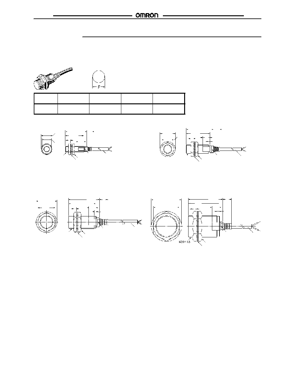
J
PREWIRED MODELS (SHIELDED)
Mounting Hole
Dimensions
Outer
diameter
M8
M12
M18
M30
F mm (in)
8.5 dia. +0.5/0
(0.33 dia. +0.02)
12.5 dia. +0.5/0
(0.49 dia. +0.02)
18.5 dia. +0.5/0
(0.73 dia. +0.02)
30.5 dia. +0.5/0
(1.2 dia. +0.02)
E2EM-X2Bj/Cj
E2EM-X8jj
E2EM-X4jj
E2EM-X15jj
Toothed washer
Two, tightening nuts
Indicator*
2
*
1
*1: Vinyl-insulated round cable (2 cores/3 cores), 4 dia. (60/0.08 dia.)
Standard length: 2 m (78.7 in)
Cable length (in single metal conduit): 200 m max.
*2: Operation indicator: yellow
Toothed washer
Two, tightening nuts
Indicator*
2
*1: Vinyl-insulated round cable (2 cores/3 cores), 4 dia.
Conductor cross-section: 0.3 mm
2
/insulator diameter: 1.3 mm
Standard length: 2 m (78.7 in)
*2: X1 models: Operation indicator: red, set indicator: green
X2 models: Operation indicator: red
B/C models: Operation indicator: yellow
Toothed washer
Two, tightening nuts
Indicator*
2
*1: Vinyl-insulated round cable (2 cores/3 cores), 6 dia.
Conductor cross-section: 0.5 mm
2
/insulator diameter: 1.9 mm
Standard length: 2 m (78.7 in)
*2: X1 models: Operation indicator: red, set indicator: green
X2 models: Operation indicator: red
B/C models: Operation indicator: yellow
*1
*
1
*1
30
(1.18)
26
(1.02)
13
(0.51)
15 dia.
(0.59 dia.)
38
(1.50)
33
(1.30)
21 dia.
(0.83 dia.)
17
(0.67)
48
(1.89)
43
(1.69)
42 dia.
(1.65 dia.)
36
(1.42)
5
12
10
3
7
8
3
M8 x 1
43
(1.69)
38
(1.50)
4
12
10
2
M8 x 1
29 dia.
(1.14 dia.)
24
(0.94)
9
4
10
2
M12 x 1
E2EM
E2EM
10
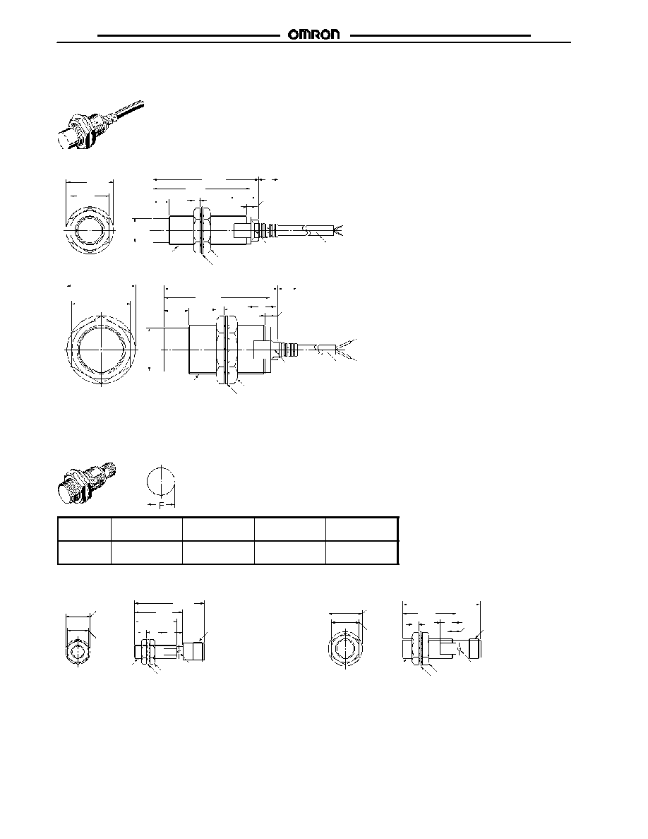
J
PREWIRED MODELS (UNSHIELDED)
E2EM-X16MXj
E2EM-X30MXj
Toothed washer
Two, tightening nuts
Indicator*
2
*1: Vinyl-insulated round cable (2 cores), 6 dia.
Conductor cross-section: 0.5 mm
2
/insulator diameter: 1.9 mm
Standard length: 2 m (78.7 in)
*2: X1 models: Operation indicator: red, set indicator: green
X2 models: Operation indicator: red
Two, tightening nuts
Indicator*
2
*1: Vinyl-insulated round cable (2 cores), 6 dia.
Conductor cross-section: 0.5 mm
2
/insulator diameter: 1.9 mm
Standard length: 2 m (78.7 in)
*2: X1 models: Operation indicator: red, set indicator: green
X2 models: Operation indicator: red
*
1
*
1
65
(2.56)
60
(2.36)
14.8 dia.
(0.58 dia.)
24
(0.94)
29 dia.
(1.14 dia.)
10
M18 x 1
36
(1.42)
12
4
10
2
42 dia.
(1.65 dia.)
65
(2.56)
70
(2.76)
26.8 dia.
(1.06 dia.)
15
10
5
3
12
M30 x 1.5
Toothed washer
J
CONNECTOR MODELS (SHIELDED)
Mounting Hole
Dimensions
Outer
diameter
M8
M12
M18
M30
F mm (in)
8.5 dia. +0.5/0
(0.33 dia. +0.02)
12.5 dia. +0.5/0
(0.49 dia. +0.02)
18.5 dia. +0.5/0
(0.73 dia. +0.02)
30.5 dia. +0.5/0
(1.2 dia. +0.02)
E2EM-X2Bj/Cj-M1
E2EM-X4Bj/Cj-M1
15 dia.
(0.59 dia.)
Toothed washer
Two, tightening nuts
Indicator*
Toothed washer
Two, tightening nuts
Indicator*
*Operation indicator: yellow
13
(0.51)
43
(1.69)
30
(1.18)
26
(1.02)
M12 x 1
M8 x 1
3
8
48
(1.89)
21 dia.
(0.83 dia.)
17
(0.67)
33
(1.30)
4
10
2
M12 x 1
M12 x 1
E2EM
E2EM
11
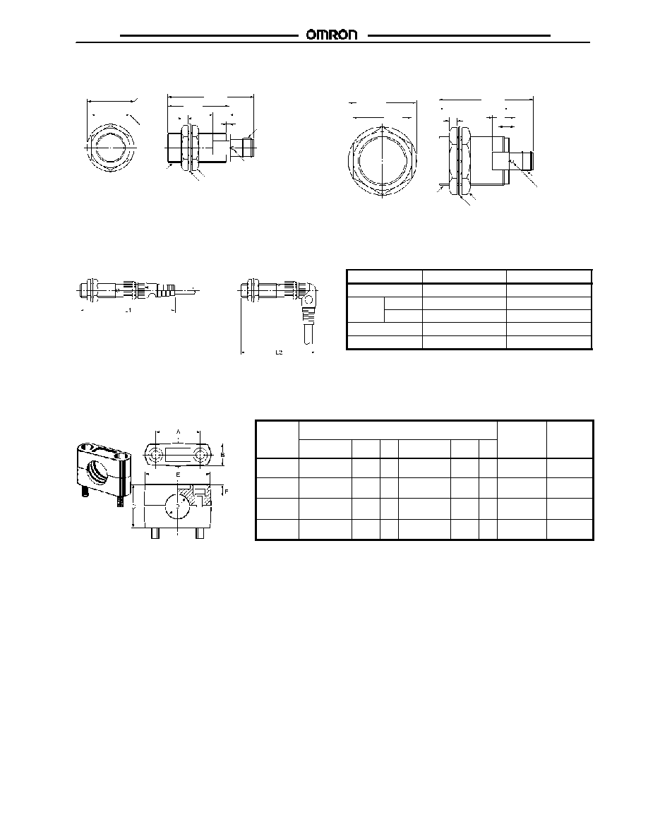
E2EM-X8Bj/Cj-M1
E2EM-X15Bj/Cj-M1
Toothed washer
Two, tightening nuts
Toothed washer
Two, tightening nuts
Indicator*
Indicator*
*Operation indicator: yellow
29 dia.
(1.14 dia.)
24
(0.94)
38
(1.50)
53
(2.09)
4
2
10
M18 x 1
M12 x 1
42 dia.
(1.65 dia.)
36
(1.42)
58
(2.28)
43
(1.69)
5
10
3
M30 x 1.5
M12 x 1
J
WHEN PROXIMITY SENSOR IS CONNECTED TO SENSOR I/O CONNECTOR
Shielded
(Straight)
(L-shaped)
Unit: mm (inch)
Sensor diameter
L1
L2
M8
Approx. 75 (2.95)
Approx. 62 (2.44)
M12
DC
Approx. 80 (3.15)
Approx. 67 (2.63)
M12
AC
Approx. 85 (3.35)
Approx. 72 (2.83)
M18
Approx. 85 (3.35)
Approx. 72 (2.83)
M30
Approx. 90 (3.54)
Approx. 77 (3.03)
J
ACCESSORIES (ORDER SEPARATELY)
Mounting Brackets
Four kinds of resin mounting brackets are available. Choose an appropriate one depending on external dimensions
Part
number
Dimensions mm (in)
Hexagonal
bolts
Applicable
Sensor
number
A
B
C
D
E
F
bolts
Sensor
outer
diameter
Y92E-B8
18�0.2
(0.71 0.01)
10
max.
18
8 dia. (0.31)
28
max.
6
M4 x 20
M8
Y92E-B12
24�0.2
(0.94 0.01)
12.5
max.
20
12 dia. (0.47) 37
max.
6
M4 x 25
M12
Y92E-B18
32�0.2
(1.26 0.01)
17
max.
30
18 dia. (0.71) 47
max.
7
M5 x 32
M18
Y92E-B30
45�0.2
(1.77 0.01)
17
max.
50
30 dia. (1.18) 60
max.
10
M5 x 50
M30
Note: When using the Mounting Brackets for unshielded models, pay attention to the influence of surrounding metals. (For dimensions of
Sensors, refer to the dimensions shown for each model.)

E2EM
E2EM
12
Installation
Connection with Sensor I/O Connectors
Proximity Sensors
Sensor I/O Connectors
Connection
Type
Operation
Part number
Sensor I/O Connectors
Connection
DC
3-wire
NO
E2EM-XjC1-M1
XS2F-D42j-jC0-A
1: Straight
2: L-shaped
D: 2-m cable
G: 5-m cable
E2EM
XS2F
Brown (+V)
Blue (0 V)
Black
(Output)
Ma
i
n
c
i
rc
u
i
t
XS2F D42j j80 A
1: Straight
2: L-shaped
E2EM
XS2F
Brown (+V)
Blue (0 V)
Black
(Output)
White (Empty)
Ma
i
n
c
i
rc
u
i
t
NC
E2EM-XjC2-M1
XS2F-D42j-j80-A
D: 2-m cable
G: 5-m cable
E2EM
XS2F
Brown (+V)
Blue (0 V)
Black
(Empty)
White (Output)
Ma
i
n
c
i
rc
u
i
t
E2EM
E2EM
13
Precautions
J
SAFETY PRECAUTIONS
Power Supply
Do not impose an excessive voltage on the E2EM, otherwise it
may be damaged. Do not impose AC current (100 VAC) on any
E2EM DC model, otherwise it may be damaged.
Load Short-circuit
Do not short-circuit the load, or the E2EM may be damaged.
The E2EM's short-circuit protection function will be valid if the
polarity of the supply voltage imposed is correct and within the
rated voltage range.
Wiring
Be sure to wire the E2EM and load correctly, otherwise it may be
damaged.
Connection with No Load
Be sure to insert loads when wiring. Make sure to connect a
proper load to the E2EM in operation, otherwise it may damage
internal elements.
Do not expose the product to flammable or explosive
gases.
Do not disassemble, repair, or modify the product.
J
CORRECT USE
Designing
Power Reset Time
The Proximity Sensor is ready to operate within 100 ms after
power is supplied. If power supplies are connected to the
Proximity Sensor and load respectively, be sure to supply power
to the Proximity Sensor before supplying power to the load.
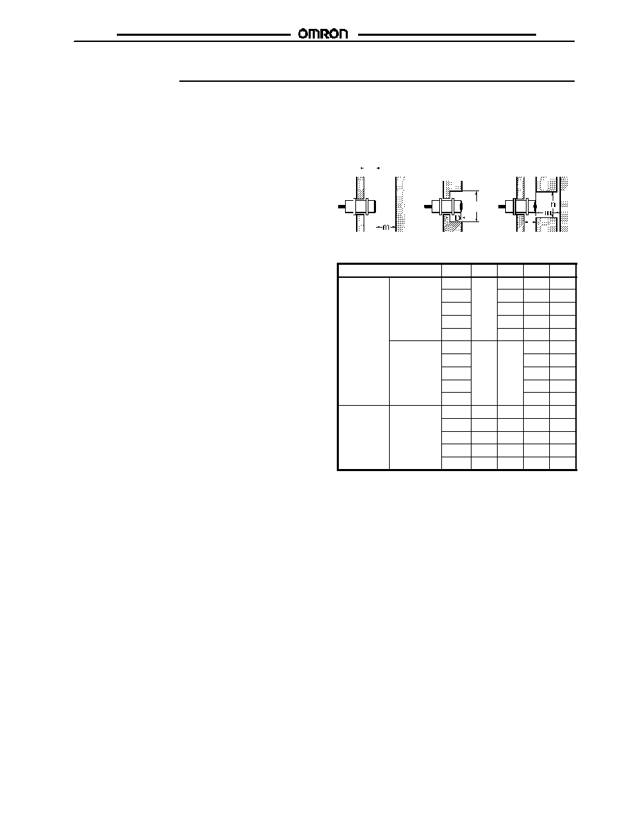
Effects of Surrounding Metal
When mounting the E2EM within a metal panel, ensure that the
clearances given in the following table are maintained.
d dia.
(Unit: mm) See note.
Type
Item
M8
M12 M18
M30
E2EM-
Shielded
---
2.4
3.6
6
E2EM
XjXj
DC 2 wire
Shielded
d
18
27
45
DC 2-wire
D
2.4
3.6
6
m
12
24
45
n
18
27
45
Unshielded
---
---
25
45
Unshielded
d
70
120
D
25
45
m
48
90
n
70
120
E2EM-
Shielded
0
2.4
3.6
6
E2EM
XjBj/Cj
DC 3 wire
Shielded
d
8
18
27
45
DC 3-wire
D
0
2.4
3.6
6
m
4.5
12
24
45
n
12
18
27
45
Note: To convert mm to inches, multiply mm's by 0.03937.
Power OFF
The Proximity Sensor may output a pulse signal when it is turned
OFF. Therefore, it is recommended that the load be turned OFF
before turning OFF the Proximity Sensor.
Power Supply Transformer
When using a DC power supply, make sure that the DC power
supply has an insulated transformer. Do not use a DC power
supply with an auto-transformer.
AND/OR Connection
When using the product in an AND/OR circuit, the product may
not function properly due to incorrect pulses or leakage currents.
Therefore, confirm that no problems will occur before actually
using the product in such a circuit.
E2EM
E2EM
14
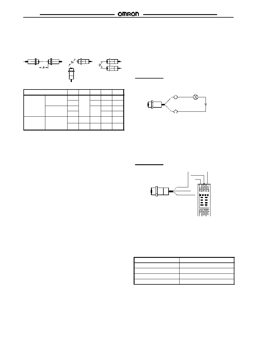
Mutual Interference
When installing two or more Sensors face-to-face or side-by-side,
ensure that the minimum distances given in the following table
are maintained.
(Unit: mm) See note.
Type
Item
M8
M12
M18
M30
E2EM-
XjXj
Shielded
A
---
30
60
110
E2EM
XjXj
DC 2-wire
Shielded
B
20
35
90
DC 2-wire
Unshielded
A
---
200
350
Unshielded
B
120
300
E2EM-
XjB/C
Shielded
A
20
30
60
110
XjB/C
DC 3-wire
B
15
20
35
90
J
DESIGNING
Confirmation of Connection between DC 2-wire Prox-
imity Sensor and Programmable Controller
Connection conditions are determined from the relationship
between the input ON voltage and OFF voltage of the PC and the
output residual voltage and leakage current of the Proximity
Sensor.
Connection Conditions
1. Relationship between the ON voltage of the PC and the
residual voltage of the Proximity Sensor must be as follows:
V
on
V
cc
-- V
R
V
on
: ON voltage of the PC
V
cc
: Supply voltage
V
R
: Output residual voltage the Proximity Sensor
2. Relationship between the OFF voltage of the PC and the
leakage current of the Proximity Sensor must be as follows:
V
off
I
leak
x R
in
V
off
: OFF voltage of the PC
I
leak
: Leakage current of the Proximity Sensor
R
in
: Input impedance of the PC
Connection is possible under the following conditions.
Example values on the PC side
ON voltage: 10.2 V min.
OFF voltage: 3 V max.
Input impedance: 3.5 k
Example values on the Proximity Sensor side
Output residual voltage: 5 V max.
Leakage current: 0.8 mA max.
If these values are put in the above formula, V
on
and V
off
will be
as follows:
V
on
: 10.2 V<24 V--5 V (=19 V)
V
off
: 3 V>0.8 mA x 3.5 k (=2.8 V)
J
WIRING
High-tension Lines
Wiring through Metal Conduit:
If there is a power or high-tension line near the cable of the
Proximity Sensor, wire the cable through an independent metal
conduit to prevent against Proximity Sensor damage or
malfunctioning.
Connections
DC 2-wire Models
Connection to relay load
Brown
Blue
24 VDC
Note: The residual voltage of the DC 2-wire model is 5 V. Check
the operating voltage of the relay.
Cable Extension
Cable length must be less than 200 m (656 ft.).
The tractive force is 50 N (11.24 lbF).
DC 3-wire Models
Connection to S3D2 Sensor Controller
Operation can be reversed
by selecting the signal input
selector of the S3D2.
Blue 0 V
Black OUT
Brown +12 V
S3D2
J
MOUNTING
The Proximity Sensor must not be subjected to excessive shock
with a hammer when it is installed, otherwise the Proximity
Sensor may be damaged or lose its water-resistivity.
Do not tighten the nut with excessive force. A washer must be
used with the nut.
Type
Torque
M8
9 N S m (79.6 in lbF)
M12
30 N S m (265 in lbF)
M18
70 N S m (619 in lbF)
M30
180 N S m (1593 in lbF)
E2EM
E2EM
J
MAINTENANCE AND INSPECTION
Periodically perform the following checks to ensure stable
operation of the Proximity Sensor over a long period of time.
1. Check for mounting position, dislocation, looseness, or
distortion of the Proximity Sensor and sensing objects.
2. Check for loose wiring and connections, improper contacts,
and line breakage.
3. Check for attachment or accumulation of metal powder or
dust.
4. Check for abnormal temperature conditions and other
environmental conditions.
5. Check for proper lighting of indicators (for models with a set
indicator.)
Never disassemble or repair the Sensor.
J
ENVIRONMENT
Water Resistance
Do not use the Proximity Sensor underwater, outdoors, or in the
rain.
Operating Environment
Be sure to use the Proximity Sensor within its operating ambient
temperature range and do not use the Proximity Sensor outdoors
so that its reliability and life expectancy can be maintained.
Although the Proximity Sensor is water resistive, a cover to
protect the Proximity Sensor from water or water-soluble
machining oil is recommended so that its reliability and life
expectancy can be maintained.
Do not use the Proximity Sensor in an environment with chemical
gas (e.g., strong alkaline or acid gasses including nitric, chromic,
and concentrated sulfuric acid gases).
J
CONNECTING LOAD TO DC 2-WIRE
SENSOR
Refer to the following before using DC 2-wire Proximity Sensors.
Surge Protection
Although the Proximity Sensor has a surge absorption circuit, if
there is any machine that has a large surge current (e.g., a motor
or welding machine) near the Proximity Sensor, connect a surge
suppressor to the machine.
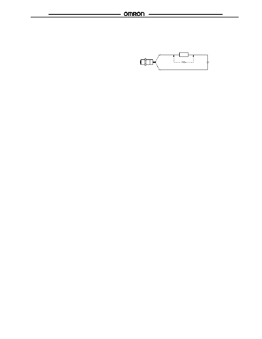
Countermeasures Against Leakage Current
Connect a bleeder resistor as the bypass for the leakage current
so that the current flowing into the load will be less than the load
reset current.
Bleeder resistor R
Load
V
S
Refer to the following to calculate the bleeder resistance and the
allowable power of the bleeder resistor.
Leakage Current
When the Proximity Sensor is OFF, the Proximity Sensor has
leakage current. In this case, the load is imposed with a small
voltage and the load may not be reset. Before using the Proximity
Sensor, make sure that this voltage is less than the load reset
voltage.
R V
S
/(i
R
-- i
OFF
) (k)
P > V
S
2
/R (mW)
P:
The allowable power of the bleeder resistor. (The actual
power capacity of the bleeder resistor must be at least a few
times larger than the allowable power of the bleeder resistor.)
i
R
: Leakage current of the Proximity Sensor (mA)
i
OFF
: Load reset current (mA)
It is recommended that 15 k max./450 mW min. for 12 VDC and
30 k max./0.1 W min. for 24 VDC be used.
Inrush Current
A load that has a large inrush current (e.g., a lamp or motor) will
damage the Proximity Sensor, in which case connect the load to
the Proximity Sensor through a relay.

ZZZ-ZZ
ZZZ-ZZ
Cat. No. CEDSAX4 11/01 Specifications subject to change without notice. Printed in U.S.A.
OMRON ELECTRONICS LLC
One East Commerce Drive
Schaumburg, IL 60173
NOTE: DIMENSIONS SHOWN ARE IN MILLIMETERS. To convert millimeters to inches divide by 25.4.
1-800-55-OMRON
OMRON CANADA, INC.
885 Milner Avenue
Scarborough, Ontario M1B 5V8
416-286-6465
R
OMRON ON--LINE
Global -- http://www.omron.com
USA -- http://www.omron.com/oei
Canada -- http://www.omron.com/oci