Document Outline
- First Page
- Ordering Information
- Specifications
- Operation
- Engineering Data
- Dimensions
- Connection
- Precautions
- Contact Omron Information
R
2
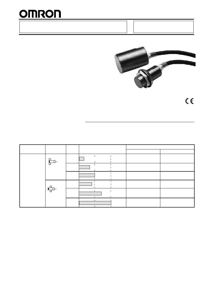
Short Barrel Inductive Prox
E2E 2-WIRE DC
Reduce Wiring to Control Devices with
Short-Barrel 2-Wire DC
Prox Sensors
H
Thick nickel-plated brass barrel has wrench
flats for easy installation
H
Solid potted internal circuitry withstands
shocks and water washdown to IP67
H
High visibility indicator
H
Choose prewired or connector models
Ordering Information
J
PREWIRED SENSORS
Self-diagnostic
Type
Size
Sensing distance
Part number
g
output function
yp
g
NO (Note.)
NC
Yes
Shielded
M12
3 mm
E2E -X3D1S
---
M18
7 mm
E2E -X7D1S
---
M30
10 mm
E2E -X10D1S
---
Unshielded
M12
8 mm
E2E -X8MD1S
---
M18
14 mm
E2E-X14MD1S
---
M30
20 mm
E2E-X20MD1S
---
Note: A different oscillating frequency i s available. Add a "5" to the part number (e.g., E2E -X3D15 ).
(This table continues on the next page.)
E2E 2-WIRE DC
E2E 2-WIRE DC
3
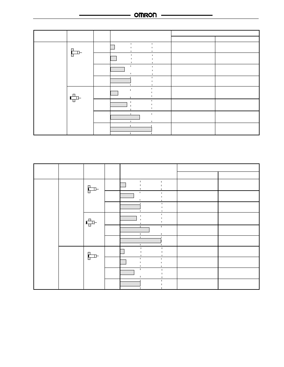
Ordering Information
-- continued from previous page
Self-diagnostic
Type
Size
Sensing distance
Part number
g
output function
yp
g
NO (Notes 1, 2.)
NC
No
Shielded
M8
2 mm
E2E -X2D1
E2E -X2D2
M12
3 mm
E2E -X3D1
E2E -X3D2
M18
7 mm
E2E -X7D1
E2E -X7D2
M30
10 mm
E2E -X10D1
E2E -X10D2
Unshielded
M8
4 mm
E2E -X4MD1
E2E -X4MD2
M12
8 mm
E2E -X8MD1
E2E -X8MD2
M18
14 mm
E2E -X14MD1
E2E -X14MD2
M30
20 mm
E2E -X20MD1
E2E -X20MD2
Note: 1. A different oscillating frequency i s available. Add a "5" to the part number (e.g., E2E -X3D15 ).
2. E2E s ensors with robotic cable are available. Add a " -R" i n the part number (e.g., E2E -X3D1 -R ).
J
SENSORS WITH BUILT-IN CONNECTOR
Connector
size
Self-diag-
nostic output
Type
Size
Sensing distance
Part number
size
nostic output
function
NO (Pins 1 and 4)
NC (Pins 1 and 2)
M12/Micro
Change
R
Yes
Shielded
M12
3 mm
E2E -X3D1S -M1
---
M18
7 mm
E2E -X7D1S -M1
---
M30
10 mm
E2E -X10D1S -M1
---
Unshielded M12
8 mm
E2E -X8MD1S -M1
---
M18
14 mm
E2E-X14MD1S-M1
---
M30
20 mm
E2E-X20MD1S-M1
---
No
Shielded
M8
2 mm
E2E -X2D1 -M1G
E2E -X2D2 -M1G
M12
3 mm
E2E -X3D1 -M1G
(See Note 1.)
E2E -X3D2 -M1G
M18
7 mm
E2E -X7D1 -M1G
(See Note 1.)
E2E -X7D2 -M1G
M30
10 mm
E2E -X10D1 -M1G
(See Note 1.)
E2E -X10D2 -M1G
Note: 1. A different oscillating frequency i s available. Add a "5" to the part number (e.g., E2E -X3D15 ).
2. E2E sensors with a "G" in the part number denotes alternate pin arrangement. Refer to the Connections section.
3. Connector cordsets: For MicroChanger use OMRON Y96E-44jDj; for NanoChanger use Omron XS3F-M42j-40j-R.
(This table continues on the next page.)
E2E 2-WIRE DC
E2E 2-WIRE DC
4
Ordering Information
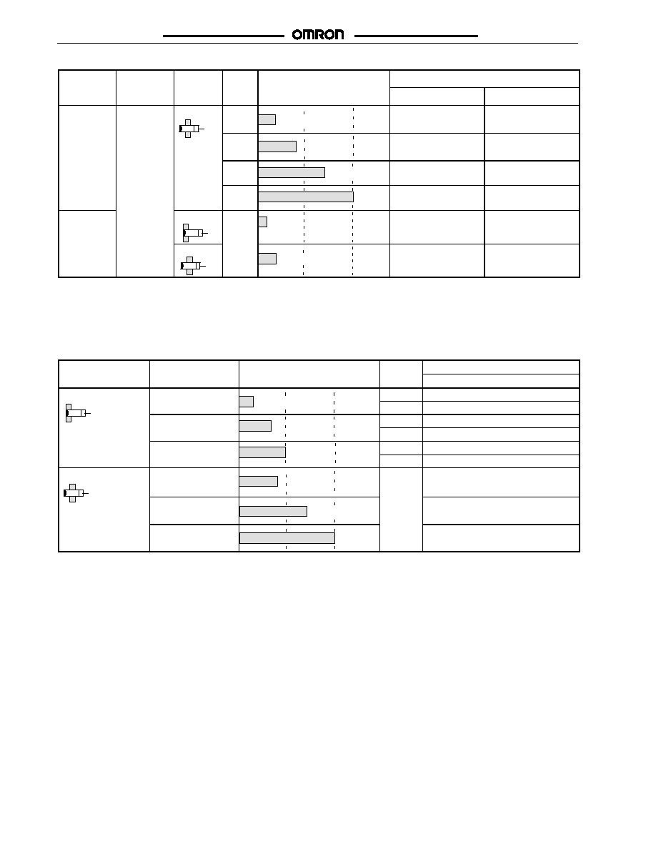
-- continued from previous page
Connector
size
Self-diag-
nostic output
Type
Size
Sensing distance
Part number
size
nostic output
function
NO (Pins 1 and 4)
NC (Pins 1 and 2)
M12/Micro
Change
R
No
Unshielded M8
4 mm
E2E -X4MD1 -M1G
E2E -X4MD2 -M1G
M12
8 mm
E2E -X8MD1 -M1G
(See Note 1.)
E2E -X8MD2 -M1G
M18
14 mm
E2E -X14MD1 -M1G
(See Note 1.)
E2E -X14MD2 -M1G
M30
20 mm E2E -X20MD1 -M1G
(See Note 1.)
E2E -X20MD2 -M1G
M8/Nano
Change
R
Shielded
M8
2 mm
E2E-X2D1-M3G
E2E-X2D2-M3G
Unshielded
4 mm
E2E-X4MD1-M3G
E2E-X4MD2-M3G
Note: 1. A different oscillating frequency i s available. Add a "5" to the part number (e.g., E2E -X3D15 ).
2. E2E sensors with a "G" in the part number denotes alternate pin arrangement. Refer to the Connections section.
3. Connector cordsets: For MicroChanger use OMRON Y96E-44jDj; for NanoChanger use Omron XS3F-M42j-40j-R.
J
SENSOR WITH PIGTAIL CONNECTOR
Type
Size
Sensing distance
Polarity
Part number
yp
g
y
NO
Shielded
M12
3 mm
Yes
E2E -X3D1 -M1GJ
3 mm
No
E 2 E -X 3 D 1 -M 1 J -T
M18
7 mm
Yes
E2E -X7D1 -M1GJ
7 mm
No
E 2 E -X 7 D 1 -M 1 J -T
M30
10 mm
Yes
E2E -X10D1 -M1GJ
10 mm
No
E2E-X10D1-M1J-T
Unshielded
M12
8 mm
Yes
E2E -X8MD1 -M1GJ
M18
14 mm
E2E -X14MD1 -M 1GJ
M30
20 mm
E2E -X20MD1 -M 1GJ
Note: 1. A model with no polarity has a residual voltage of 5 V, which must be taken into consideration together with the interface
condition (the PLC's ON voltage, for example) when connecting the proximity sensor to a load.
2. Connector cordsets: Use OMRON Y96E-44jDj.
E2E 2-WIRE DC
E2E 2-WIRE DC
5
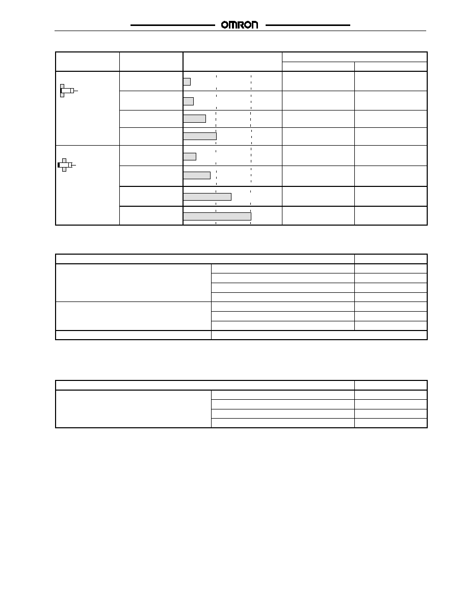
J
SENSOR WITH FOUR-PIN CONNECTOR
Type
Size
Sensing distance
Part number
yp
g
NO (Pins 3 and 4)
NC (Pins 2 and 3)
Shielded
M8
2 mm
E2E -X2D1 -M1
E2E -X2D2 -M1
M12
3 mm
E2E -X3D1 -M1
E2E -X3D2 -M1
M18
7 mm
E2E -X7D1 -M1
E2E -X7D2 -M1
M30
10 mm
E2E -X10D1 -M1
E2E -X10D2 -M1
Unshielded
M8
4 mm
E2E -X4MD1 -M1
E2E -X4MD2 -M1
M12
8 mm
E2E -X8MD1 -M1
E2E -X8MD2 -M1
M18
14 mm
E2E -X14MD1 -M1
E2E -X14MD2 -M1
M30
20 mm
E2E -X20MD1 -M1
E2E -X20MD2 -M1
J
ACCESSORIES
Description
Part number
Mounting brackets
Fits M8 size sensors
Y92E-B8
g
Fits M12 size sensors
Y92E-B12
Fits M18 size sensors
Y92E-B18
Fits M30 size sensors
Y92E-B30
Silicone rubber covers for shielded sensors
Fits M12 size sensors
Y92E-E12-2
Fits M18 size sensors
Y92E-E18-2
Fits M30 size sensors
Y92E-E30-2
Connector cordsets
See Y96E and XS Connector Cordsets data sheets for details
Note: Use OMRON Y96E-44jDj cordsets with M12 connector; use XS3F cordsets with M8 connector.
J
REPLACEMENT PARTS
Description
Part number
Mounting hardware including one pair of metal nuts
d
h
Fits M8 size sensors
M8-MHWS
g
g
p
and one washer
Fits M12 size sensors
M12-MHWS
Fits M18 size sensors
M18-MHWS
Fits M30 size sensors
M30-MHWS

E2E 2-WIRE DC
E2E 2-WIRE DC
6
Specifications
J
RATINGS/CHARACTERISTICS
Part number
E2E-X2Dj
E2E-X4MD j
E2E-X3Dj
E2E-X8MD j
E2E-X7Dj
E2E-X14MD j
E2E-X10D j
E2E-X20MD j
Size
M8
M12
M18
M30
Type
Shielded
Unshielded
Shielded
Unshielded
Shielded
Unshielded
Shielded
Unshielded
Sensing distance
2 mm (0.08
in) �10%
4 mm (0.16
in) �10%
3 mm (0.12
in) �10%
8 mm (0.31
in) �10%
7 mm (0.28
in) �10%
14 mm (0.55
in) �10%
10 mm
(0.39 in)
�10%
20 mm (0.79
in) �10%
Supply voltage
(operating voltage)
12 to 24 VDC, ripple (p-p): 10% max., (10 to 30 VDC)
Leakage current
0.8 mA max.
Sensing object
Magnetic metals (refer to Engineering Data for non-magnetic metals)
Setting distance
0 to 1.6
mm (0 to
0.06 in)
0 to 3.2 mm
(0 to 0.13
in)
0 to 2.4
mm (0 to
0.09 in)
0 to 6.4 mm
(0 to 0.25
in)
0 to 5.6
mm (0 to
0.22 in)
0 to 11.2 mm
(0 to 0.44 in)
0 to 8.0 mm
(0 to 0.31
in)
0 to 16.0 mm
(0 to 0.63 in)
Standard object
(mild steel)
8 x 8 x
1 mm (0.31
x 0.31 x
0.04 in)
20 x 20 x
1 mm (0.79
x 0.79 x
0.04 in)
12 x 12 x
1 mm (0.47
x 0.47 x
0.04 in)
30 x 30 x
1 mm
(1.18 x 1.18
x 0.04 in)
18 x 18 x
1 mm (0.71
x 0.71 x
0.04 in)
30 x 30 x
1 mm
(1.18 x 1.18
x 0.04 in)
30 x 30 x
1 mm
(1.18 x 1.18
x 0.04 in)
54 x 54 x
1 mm
(2.13 x 2.13
x 0.04 in)
Differential travel
15% max. of sensing
distance
10% max. of sensing distance
Response frequency 1.5 kHz
1.0 kHz
1.0 kHz
0.8 kHz
0.5 kHz
0.4 kHz
0.4 kHz
0.1 kHz
Operation (with
target object
approaching)
D1 models: Load ON
D2 models: Load OFF
Control output
(switching
capacity)
3 to 100 mA (5 to 100 mA with residual voltage of 5V for -M1J-T models)
Diagnostic output: 50 mA for -D1S models
Diagnostic output
delay
0.3 to 1 s
Circuit protection
Surge absorber, load short-circuit protection (for control and diagnostic output)
Indicator
D1 models: Operation indicator (red LED), operation set indicator (green LED)
D2 models: Operation indicator (red LED)
Ambient
temperature
Operating: --25�C to 70�C (--13�F to 158�F) with no icing
Ambient humidity
Operating: 35% to 95%
Temperature
influence
�15% max. of sensing
distance at 23�C in temp-
erature range of --25�C to
70�C (--13�F to 158�F)
�10% max. of sensing distance at 23�C in temperature range of --25�C to 70�C
(--13�F to 158�F)
Voltage influence
�1% max. of sensing distance in rated voltage range �15%
Residual voltage
3.0 V max. (under load current of 100 mA with cable length of 2 m)
5.0 V min. for -M1J-T models
Insulation resistance 50 M min. (at 500 VDC) between current carry parts and case
Dielectric strength
1,000 VAC for 1 min between current carry parts and case
Vibration resistance
10 to 55 Hz, 1.5-mm double amplitude for 10 times each in X, Y, and Z axes
Shock resistance
500 m/s
2
(approx. 50G)
for 10 times each in X, Y,
and Z axes
1,000 m/s
2
(approx. 100G) for 10 times each in X, Y, and Z axes
Enclosure
IEC
IP67
rating
NEMA
1, 4, 6, 12, 13
Weight
Approx. 45 g
Approx. 120 g
Approx. 160 g
Approx. 220 g
Material
Body
Stainless steel
Brass
Sensing
face
PBT
E2E 2-WIRE DC
E2E 2-WIRE DC
7
Operation
J
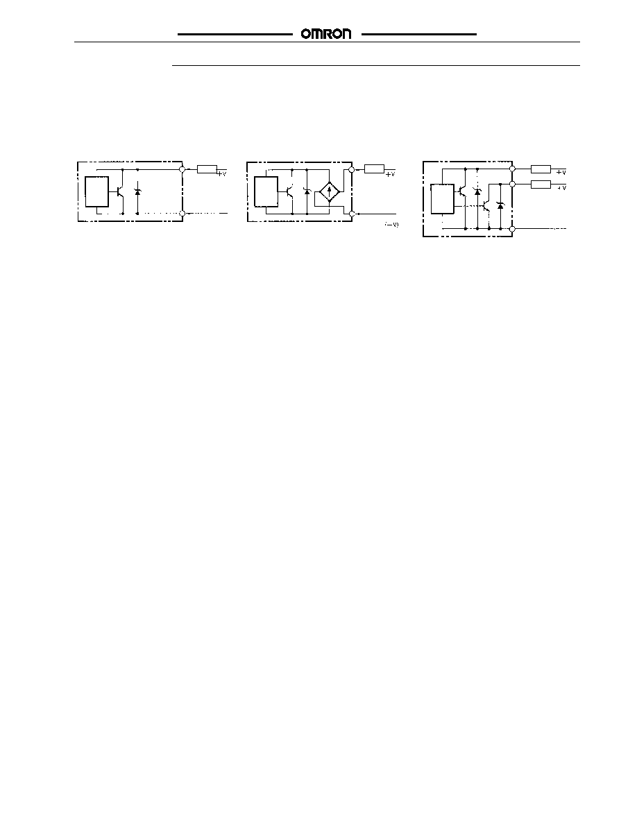
OUTPUT CIRCUITS
E2E -X jDj DC 2 -wire Models
E2E -X j Dj
Without Diagnostic Output
E2E -X j D 1 -M 1 J -T
No Polarity
E2E -X j D1S
With Diagnostic Output
Note:
1. The load can be connected to
either the +V or 0-V side.
2. The E2E-XjD1-M1J-T has no
polarity. Therefore, terminals 3
and 4 have no polarity.
Main
circuit
Load
Brown
4 (or 2)
Blue
0 V
Main
circuit
(0 V)
0 V
1
3
4
Main
circuit
Brown
Blue
0 V
4
Load
Load
Load
2
Orange (diagnostic
output)
3
Short-Circuit Indication
The LED dims when the load is shorted and the load output immediately turns off and remains off until the short-circuit protection is reset.
Resetting Short-Circuit Protection
Before the short-circuit protection can be reset, the short must be repaired. We recommend turning the power off before repairing the
short. If this approach is taken, no further action is required to reset the short-circuit protection.
If the short must be repaired with power on, the following resetting steps are required:
For NO sensors, the target must be removed to reset the short-circuit protection.
For NC sensors, the target must be presented then removed to reset the short-circuit protection.
E2E 2-WIRE DC
E2E 2-WIRE DC
8
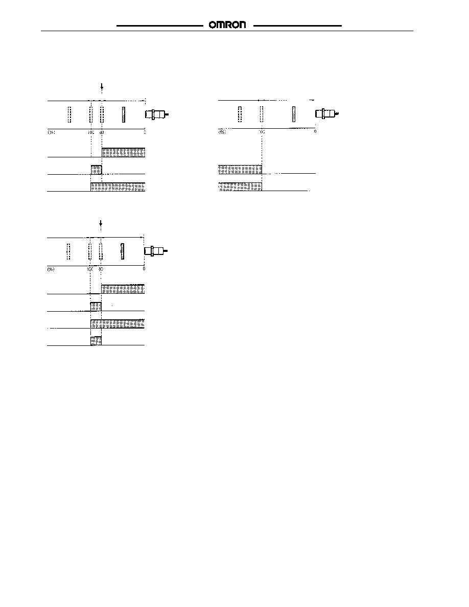
J
OPERATING CHARTS
E2E -X j D1
NO Type
E2E -X j D2
NC Type
Non-sensing
zone
Unstable
sensing zone
Setting
position
Stable sensing
zone
Sensing
object
Proximity
Sensor
Rated
s
ens
ing
dis
t
anc
e
Rated
s
ens
ing
dis
t
anc
e
Non-sensing zone
Stable sensing
zone
Lit
Not lit
Green
indicator
Lit
Not lit
Red
indicator
Control
output
Sensing zone
Proximity
Sensor
Lit
Not lit
Control
output
Sensing
object
ON
OFF
Red
indicator
ON
OFF
E2E -X j D1S
Note: The diagnostic output of the E 2E -X j D1S is ON when
there is a coil burnout or the sensing object is located in the
unstable sensing range for 0.3 s or more.
Non-sensing
zone
Unstable
sensing zone
Setting
position
Stable sensing
zone
Sensing
object
Proximity
Sensor
Rated
s
ens
ing
dis
t
anc
e
Lit
Not lit
Green
indicator
Lit
Not lit
Diagnostic
output
Control
output
Red
indicator
ON
OFF
ON
OFF
E2E 2-WIRE DC
E2E 2-WIRE DC
9
Engineering Data
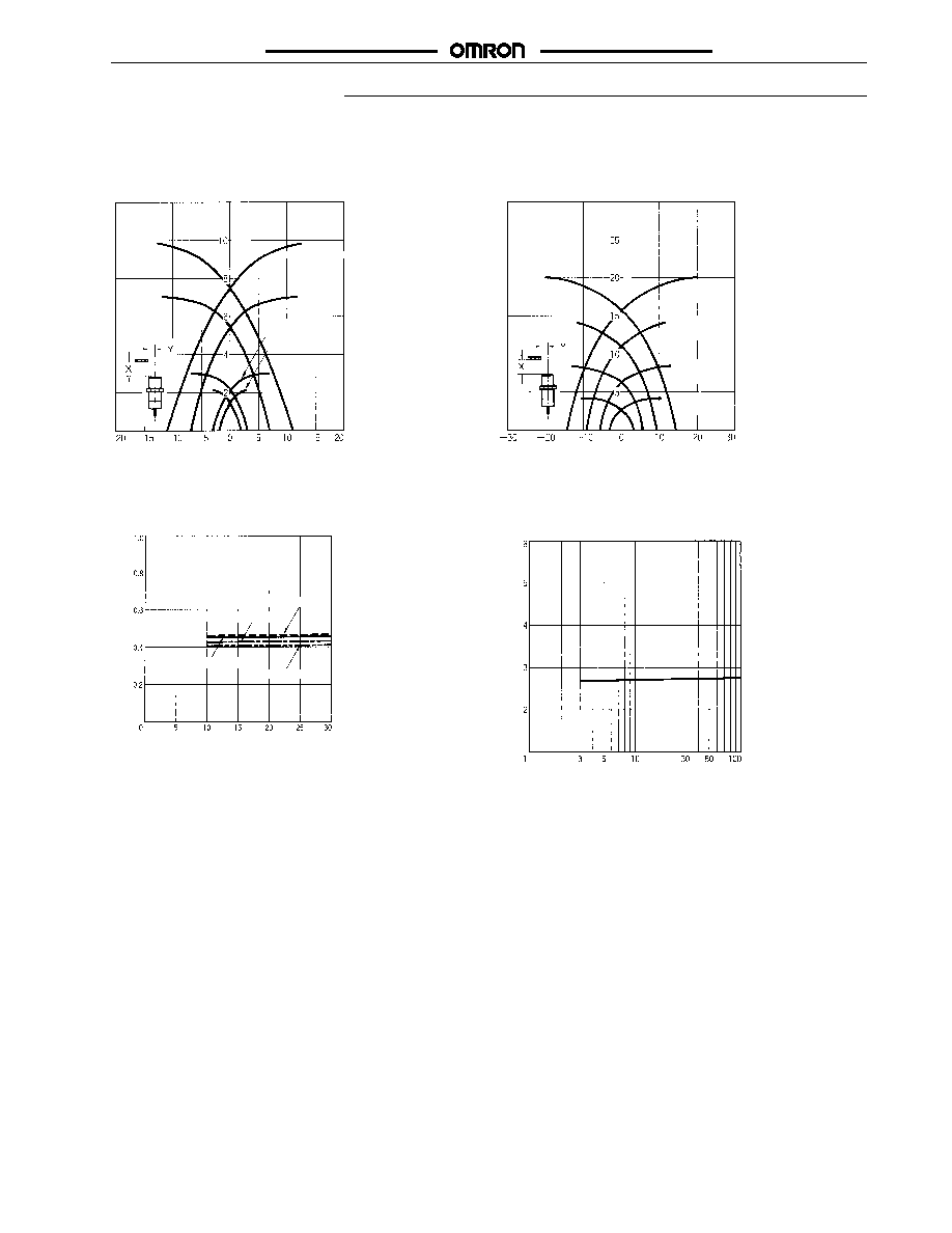
J
OPERATING RANGE (TYPICAL)
Shielded Models
Unshielded Models
E2E -X j Dj E 2 E - j MDj
E2Ej-X10D/Tj
Sensi
n
g
d
i
s
tance
X
(mm)
E2Ej-X7D/Tj
E2Ej-X3D/Tj
E2E-X2Dj
Y (mm)
E2Ej-X20MDj
E2Ej-X14MDj
E2Ej-X8MDj
E2Ej-
X4MDj
S
e
n
sin
g
d
ista
n
ce
X
(mm)
Y (mm)
J
LEAKAGE CURRENT (TYPICAL)
E2E -X j Dj
Leakage
current
(mA)
Supply voltage (V)
E2E-X10D1
E2E-X3D1
E2E-X2D1
E2E-X7D1
J
RESIDUAL OUTPUT VOLTAGE (TYPICAL)
E2E -X j Dj
Residual
output
voltage
(V)
Load current (mA)
E2E 2-WIRE DC
E2E 2-WIRE DC
10
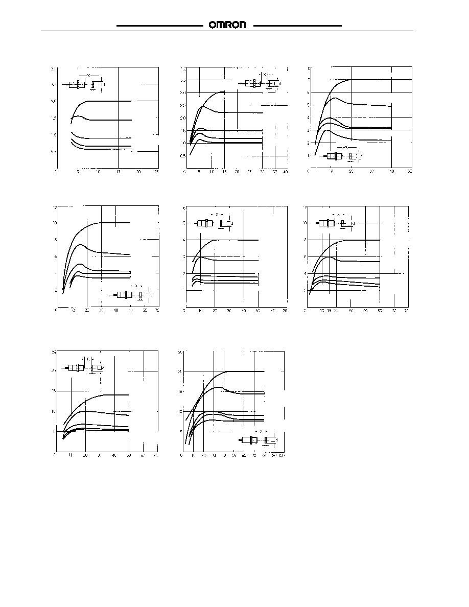
J
SENSING DISTANCE VS. SENSING OBJECT (TYPICAL)
E2E -X 2Dj
E 2 E - 3Dj
E 2 E -7Dj
E2E -X10Dj
E2E -X4MDj E2E -X8MDj
Mild steel
Stainless steel
(SUS304)
Copper
Mild
steel
Brass
Aluminum
Copper
Brass
Copper
Stainless steel
(SUS304)
Stainless steel
(SUS304)
Brass
Aluminum
t = 1 mm
t = 1 mm
t = 1 mm
Aluminum
Mild
steel
Copper
Mild
steel
Brass
Aluminum
Copper
Mild
steel
Brass
Aluminum
Copper
Stainless
steel
(SUS304)
Stainless
steel
(SUS304)
Stainless
steel
(SUS304)
Brass
Aluminum
t = 1 mm
t = 1 mm
t = 1 mm
Sensing
d
istance
(
mm)
Side length of target object d (mm)
Sensing
d
istance
(
mm)
Sensing
d
istance
(
mm)
Sensing
d
istance
(
mm)
Sensing
d
istance
(
mm)
Sensing
d
istance
(
mm)
Mild steel
Side length of target object d (mm)
Side length of target object d (mm)
Side length of target object d (mm)
Side length of target object d (mm)
Side length of target object d (mm)
E2E -X14MDj
E2E -X20MDj
Mild
steel
Copper
Stainless
steel
(SUS304)
Brass
Aluminum
Mild
steel
Copper
Stainless
steel
(SUS304)
Brass
Aluminum
t = 1 mm
t = 1 mm
Sensing
d
istance
(
mm)
Side length of target object d (mm)
Sensing
d
istance
(
mm)
Side length of target object d (mm)

E2E 2-WIRE DC
E2E 2-WIRE DC
11
Dimensions
J
DRAWING LOCATOR
Type
Part number
Figure number
Pre-wired
Shielded
M8
E2E -X2Dj
1
M12
E2E -X3Dj
3
M18
E2E -X7Dj
5
M30
E2E -X10Dj
7
Unshielded
M8
E2E -X4MDj
2
M12
E2E -X8MDj
4
M18
E2E -X14MDj
6
M30
E2E -X20MDj
8
4-Pin connector
Shielded
M8
E2E -X2Dj -M 1 G
9
(M12)
M12
E2E -X3Dj -M 1 G
11
M18
E2E -X7Dj -M 1 G
13
M30
E2E -X10Dj -M 1 G
15
Unshielded
M8
E2E -X4MDj -M 1 G
10
M12
E2E -X8MDj -M 1 G
12
M18
E2E -X14MDj -M 1 G
14
M30
E2E -X20MDj -M 1 G
16
M8 connector
Shielded
M8
E2E -X2Dj -M 3 G
17
Unshielded
E2E -X4MDj -M 3 G
18
Pigtail connector
Shielded
M12
E2E -X3D1 -M1GJ
19
g
M18
E2E -X7D1 -M1GJ
21
M30
E2E -X10D1 -M1GJ
23
Unshielded
M12
E2E -X8MD1 -M1GJ
20
M18
E2E -X14MD1 -M 1GJ
22
M30
E2E -X20MD1 -M 1GJ
24
Pigtail connector, no Shielded
M12
E 2 E -X 3 D 1 -M 1 J -T
25
g
,
polarity
M18
E 2 E -X 7 D 1 -M 1 J -T
26
M30
E2E -X10D1 -M1J -T
27
E2E 2-WIRE DC
E2E 2-WIRE DC
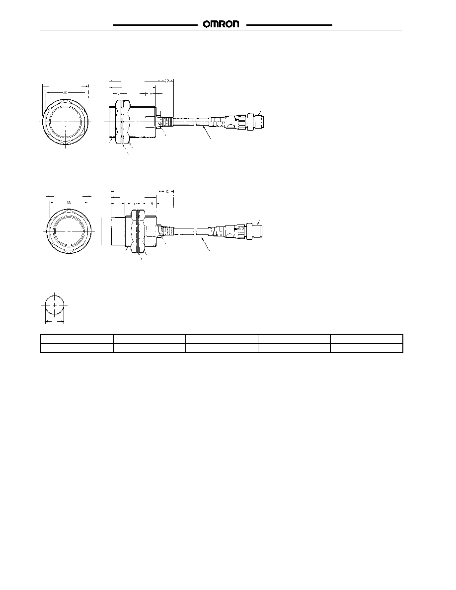
12
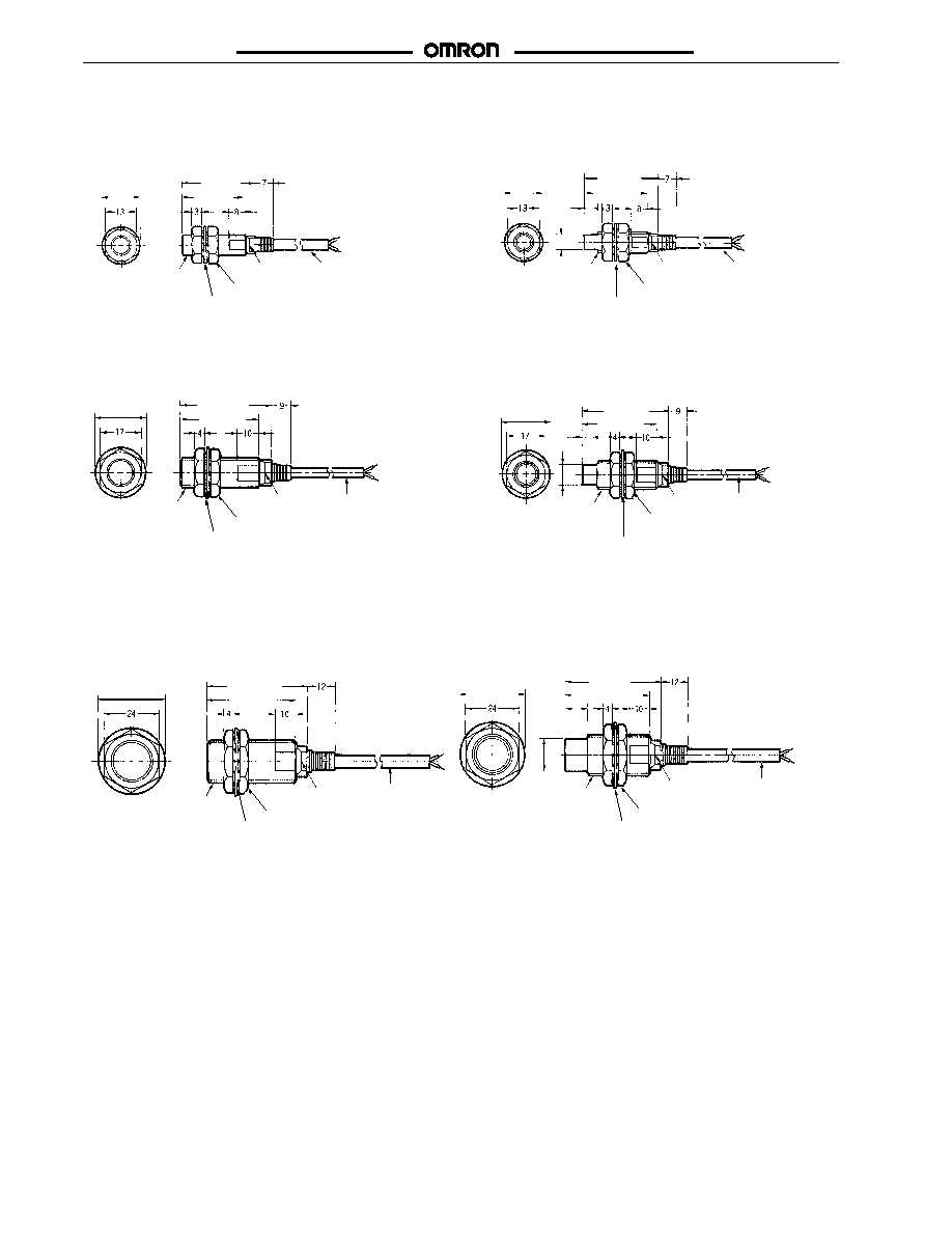
Unit: mm (inch)
Fig. 1: E2E -X2D j
Prewired Models
(Shielded)
Prewired Models
(Unshielded)
Fig. 2: E2E -X4MDj
Fig. 3: E2E -X3D j Fig. 4: E2E -X8MDj
M12 x 1
Operation
indicator
Two clamping nut
Toothed washer
Round vinyl-insulated cable
4 dia. (0.08 dia. x 60),
2/3 cores
4 dia. (0.08 dia. x 6/10) for
robotics cable models
Standard length: 2 m
Round vinyl-insulated cable
4 dia. (0.08 dia. x 60),
2/3 cores
4 dia. (0.08 dia. x 6/10) for
robotics cable models
Standard length: 2 m
9 dia.
M12 x 1
Operation
indicator
Two clamping
nut
Toothed washer
M8 x 1
Operation
indicator
Two clamping nut
Toothed washer
Round vinyl-insulated cable
4 dia. (0.08 dia. x 60),
2/3 cores
4 dia. (0.08 dia. x 6/10) for
robotics cable models
Standard length: 2 m
15 dia. (0.59)
M8 x 1
Operation
indicator
Two clamping nut
Toothed washer
Round vinyl-insulated cable
4 dia. (0.08 dia. x 60),
2/3 cores
4 dia. (0.08 dia. x 6/10) for
robotics cable models
Standard length: 2 m
6.1 dia.
30 (1.18)
26 (1.02)
15 dia. (0.59)
30 (1.18)
6
(0.24)
21 dia. (0.83)
38 (1.50)
21 dia. (0.83)
38 (1.50)
33 (1.30)
7
(0.28)
26 (1.02)
33 (1.30)
Prewired Models
(Shielded)
Prewired Models
(Unshielded)
Fig. 5: E2E -X7D j Fig. 6: E2E -X14MD j
Operation
indicator
Two clamping nut
Toothed washer
M18 x 1
M18 x 1
Operation
indicator
Two clamping nut
Toothed washer
14.8 dia.
Round vinyl-insulated Cable
6 dia. (0.12 dia. x 45),
2/3 cores
6 dia. (0.08 dia. x 6/17)
robotics cable models
Standard length: 2m
Round vinyl-insulated
Cable 6 dia. (0.12 dia.
x 45), 2/3 cores
6 dia. (0.08 dia. x 6/17)
robotics cable models
Standard length: 2m
43 (1.69)
10
(0.39)
29 dia. (1.14)
29 dia. (1.14)
43 (1.69)
38 (1.50)
38 (1.50)
E2E 2-WIRE DC
E2E 2-WIRE DC
13
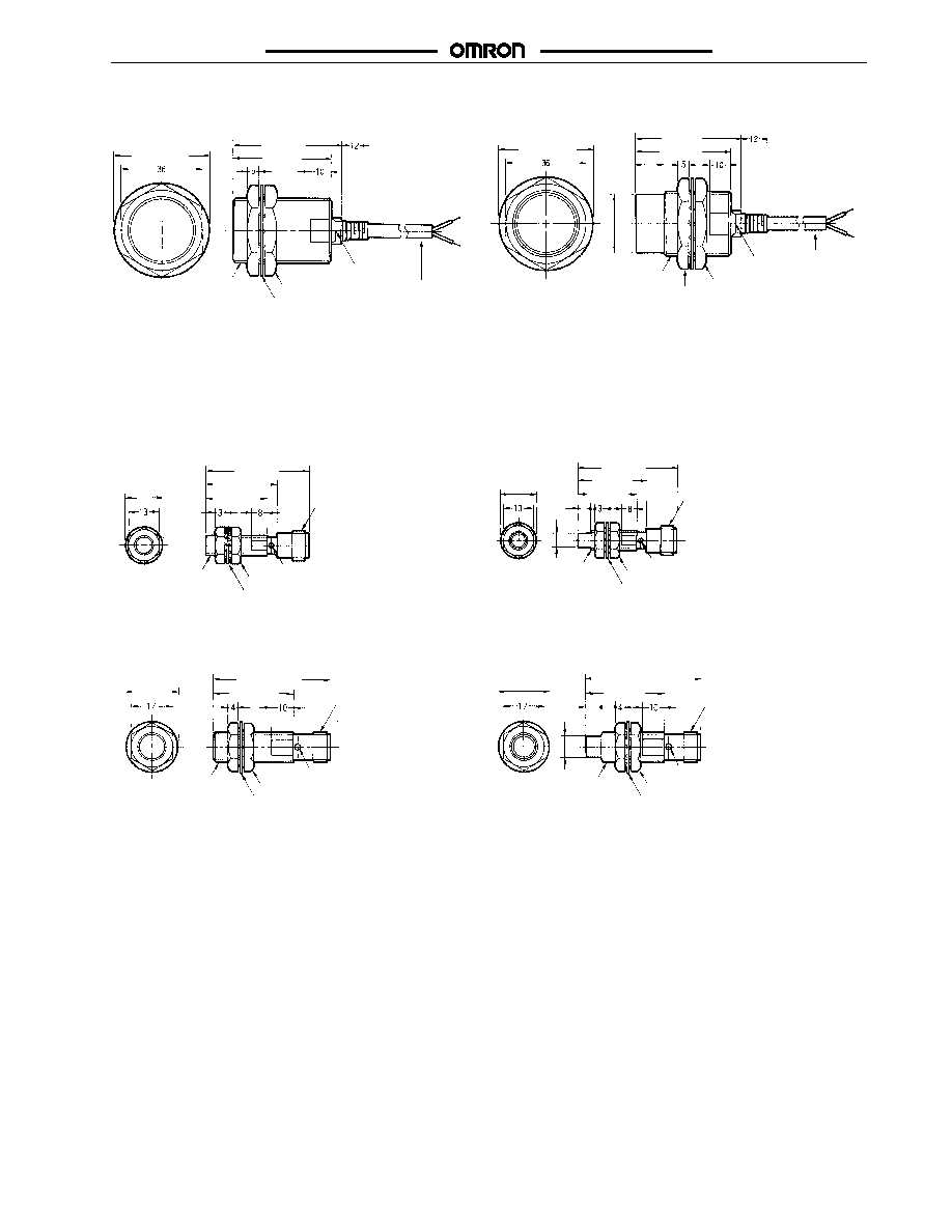
Unit: mm (inch)
Fig. 7: E2E -X 10Dj Fig. 8: E2E -X 20MDj
M30 x 1.5
Operation indicator
Two clamping nut
Toothed washer
M30 x 1.5
Operation
indicator
Two clamping
nut
Toothed washer
26.8 dia.
Round vinyl-insulated
Cable 6 dia. (0.12 dia.
x 45), 2/3 cores
6 dia. (0.08 dia. x 6/17)
robotics cable models
Standard length: 2m
Round vinyl-insulated Cable
6 dia. (0.12 dia. x 45),
2/3 cores
6 dia. (0.08 dia. x 6/17)
robotics cable models
Standard length: 2m
48 (1.89)
43 (1.69)
42 dia. (1.65)
13
(0.51)
48 (1.89)
43 (1.69)
42 dia. (1.65)
Fig. 9: E2E -X2D j -M 1 G Fig. 10: E2E -X4MDj -M 1 G
Operation indicator
Two clamping nut
Toothed washer
M8 x 1
M12 x 1
Operation indicator
Two clamping nut
Toothed washer
M8 x 1
M12 x 1
6.1 dia.
15 dia. (0.59)
30 (1.18)
43 (1.69)
6
(0.24)
15 dia. (0.59)
30 (1.18)
26 (1.02)
43 (1.69)
26 (1.02)
Connector Models
(Shielded)
Connector Models
(Unshielded)
Fig. 11: E 2E -X 3Dj -M 1G Fig. 12: E2E -X8MDj -M 1 G
Operation indicator
Two clamping nut
Toothed washer
M12 x 1
M12 x 1
Operation indicator
Two clamping nut
Toothed washer
M12 x 1
M12 x 1
9 dia.
48 (1.89)
33 (1.30)
21 dia. (0.83)
48 (1.89)
33 (1.30)
21 dia. (0.83)
7
(0.28)
E2E 2-WIRE DC
E2E 2-WIRE DC
14
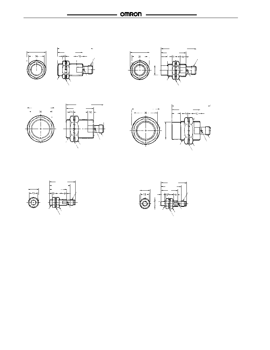
Connector Models
(Shielded), continued
Connector Models
(Unshielded), continued
Fig. 13
E2E-X7Dj-M1G
Fig. 14:
E2E-X14MDj-M1G
Fig. 15:
E2E-X10Dj-M1G
Fig. 16:
E2E-X20MDj-M1G
M30 x 1.5
Operation indicator
Two clamping nut
Toothed washer
M12 x 1
M30 x 1.5
Operation indicator
Two clamping nut
Toothed washer
M12 x 1
26.8 dia.
Operation indicator
Two clamping nut
Toothed washer
M12 x 1
M18 x 1
M12 x 1
M18 x 1
Operation indicator
Two clamping nut
Toothed washer
14.8 dia.
53 (2.09)
38 (1.50)
29 dia. (1.14)
53 (2.09)
38 (1.50 )
29 dia. (1.14)
10
(0.39)
58 (2.28)
43 (1.69)
42 dia. (1.65)
58 (2.28)
43 (1.69)
42 dia. (1.65)
13
(0.51)
Fig. 17:
E2E-X2Dj-M3G
M8 Connector Models
(Shielded)
M8 Connector Models
(Unshielded)
Fig. 18:
E2E-X4MDj-M3G
M8 x 1
Operation indicator
Two clamping nut
Toothed washer
M8 x 1
M8 x 1
Operation indicator
Two clamping nut
Toothed washer
M8 x 1
6.1 dia.
39 (1.54)
15 dia. (0.59)
31 (1.22)
26
(1.02)
39 (1.54)
15 dia. (0.59)
31 (1.22)
26
(1.02)
6
(0.24)
E2E 2-WIRE DC
E2E 2-WIRE DC
15
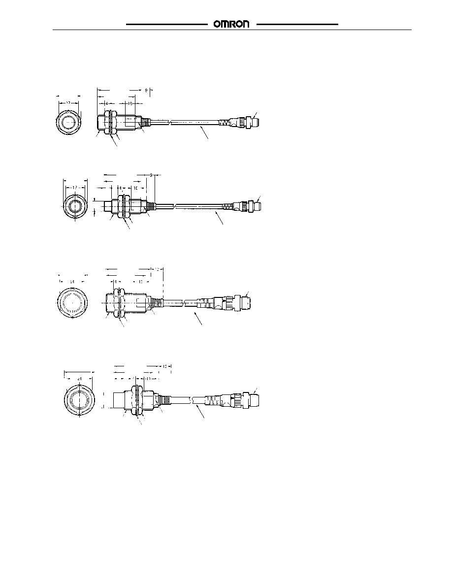
Unit: mm (inch)
J
PIGTAIL CONNECTOR
Fig. 19: E2E -X3D1 -M 1GJ
E 2 E -X 3 D 1 -M 1 J -T
Fig. 20: E2E -X8MD1 -M1GJ
Fig. 21: E2E -X7D1 -M 1GJ
E 2 E -X 7 D 1 -M 1 J -T
M12 x 1
M18 x 1
Operation indicator
Two clamping nut
Toothed washer
Round vinyl-insulated cable
6 dia. (0.12 dia. x 45)
Standard length: 0.3 m
Operation indicator
Two clamping nut
Toothed washer
M12 x 1
Round vinyl-insulated cable
4 dia. (0.08 dia. x 60)
Standard length: 0.3 m
M12 x 1
M12 x 1
M12 x 1
Operation indicator
Two clamping nut
Toothed washer
Round vinyl-insulated cable
4 dia. (0.08 dia. x 60)
Standard length: 0.3 m
9 dia.
38 (1.50)
21 dia. (0.83)
38 (1.50)
21 dia. (0.83)
33 (1.30)
7
(0.28)
43 (1.69)
29 dia. (1.14)
38 (1.50)
33 (1.30)
Fig. 22: E2E -X14MD1 -M 1GJ
M12 x 1
M18 x 1
Operation indicator
Two clamping nut
Toothed washer
Round vinyl-insulated cable
6 dia. (0.12 dia. x 45)
Standard length: 0.3 m
43 (1.69)
29 dia. (1.14)
38 (1.50)
10
(0.39)
14.8 dia.
E2E 2-WIRE DC
E2E 2-WIRE DC
16
Fig. 23: E2E -X10D1 -M1GJ
E2E-X10D1-M1J-T
Fig. 24: E2E -X20MD1 -M 1GJ
Mounting Holes
M30 x 1.5
M12 x 1
Operation indicator
Two clamping nut
Toothed washer
26.8 dia.
M30 x 1.5
Operation indicator
Two clamping nut
Toothed washer
M12 x 1
F
Round vinyl-insulated cable
6 dia. (0.12 dia. x 45)
Standard length: 0.3 m
Round vinyl-insulated cable
6 dia. (0.12 dia. x 45)
Standard length: 0.3 m
48 (1.89)
42 dia. (1.65)
43 (1.69)
48 (1.89)
43 (1.69)
42 dia. (1.65)
13
(0.51)
Pigtail Connector Models, continued
Dimensions
M8
M12
M18
M30
F (mm)
8.5
+0.5
/
0
dia.
12.5
+0.5
/
0
dia.
18.5
+0.5
/
0
dia.
30.5
+0.5
/
0
dia.
E2E 2-WIRE DC
E2E 2-WIRE DC
17
Connection
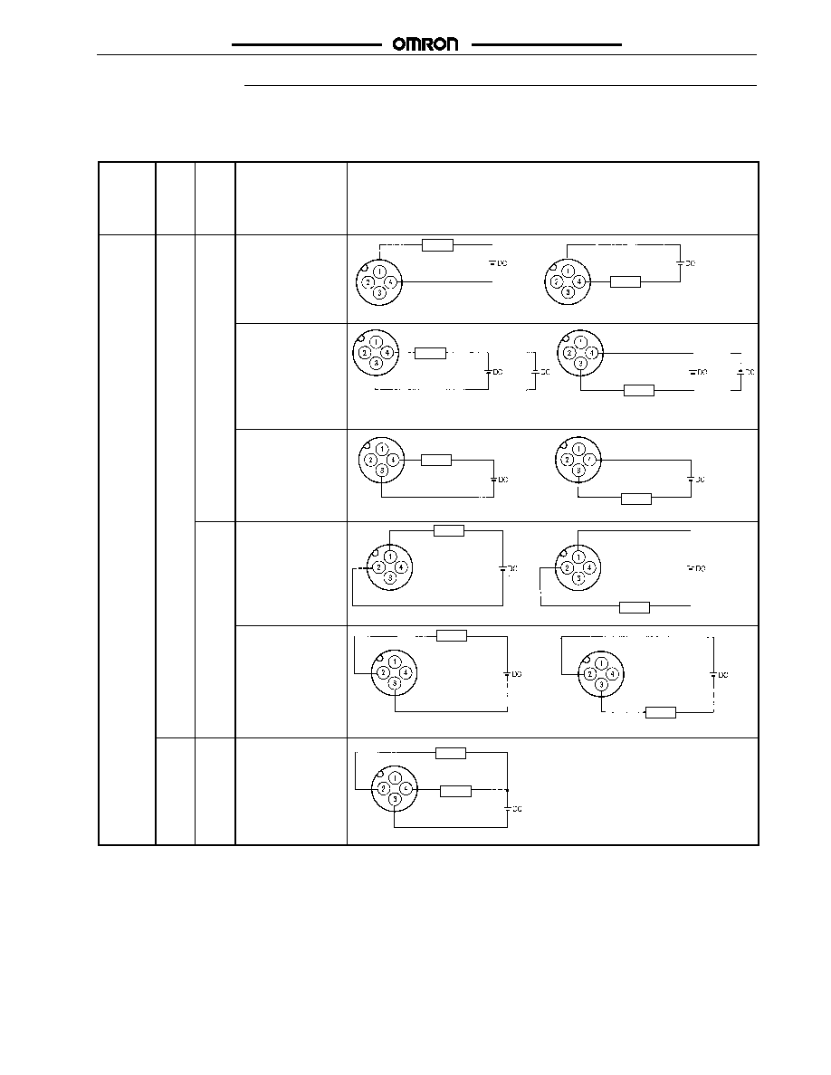
J
PIN ARRANGEMENTS
E2E -X jDj -M j DC 2 -wire Models
Connector Self-
diag-
nostic
output
Out-
put
con-
figura-
tion
Applicable models
Pin arrangement
M12
Micro
Change
R
No
NO
E2 E- Xj D1 - M 1 Gj
(See Note.)
Note:
Terminals 2 and 3 are not used.
Load
Load
E2 E- Xj D1 -M1J-T
Note:
1. Terminals 1 and 2 are not used.
2. Terminals 3 and 4 have no polarity.
Load
Load
or
or
E2 E- Xj D1 - M 1
Note:
Terminals 1 and 2 are not used.
Load
Load
NC
E2 E- Xj D2 -M1G
(See Note.)
Note:
Terminals 3 and 4 are not used.
Load
Load
E2 E- Xj D2 - M 1
Note:
Terminals 1 and 4 are not used.
Load
Load
Yes
NO
E2 E- Xj D1 S- M1
Note:
Terminal 1 is not used.
Load
Load
(Control output)
Note:
Pin arrangements conform to IEC standards.
(This table continues on the next page.)
E2E 2-WIRE DC
E2E 2-WIRE DC
18
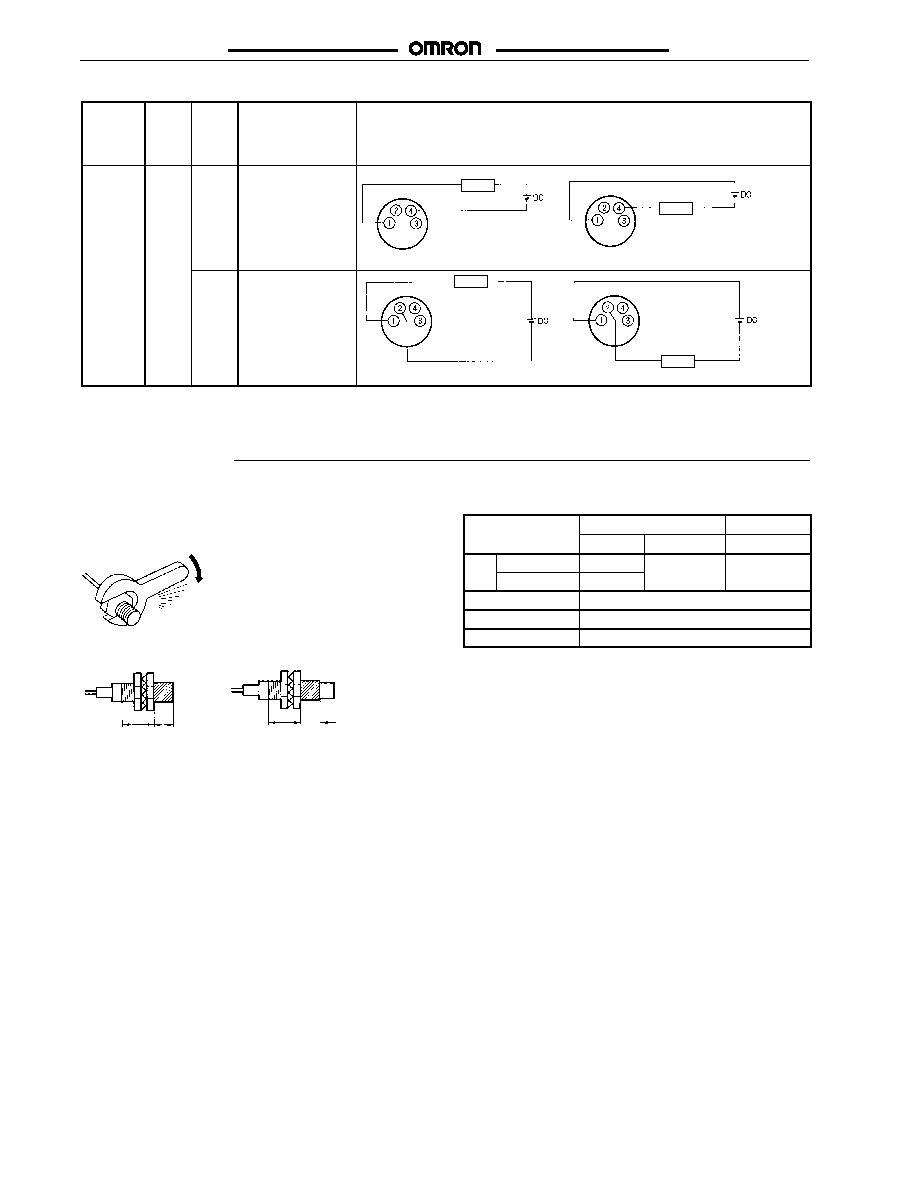
J
PIN ARRANGEMENT (CONTINUED)
Connector Self-
diag-
nostic
output
Output
config-
uration
Applicable models
Pin arrangement
M8 Nano
Change
R
No
NO
E2 E- Xj D1 -M3G
Note:
Terminals 2 and 3 are not used.
Load
Load
NC
E2 E- Xj D2 -M3G
Note:
Terminals 3 and 4 are not used.
Load
Load
Precautions
J
MOUNTING
Do not tighten the nut with excessive force. A washer must be used
with the nut.
Shielded Model
Unshielded Model
Part B Part A
Part B Part A
Note:
The table above right shows the tightening torques for part
A and part B nuts. In the previous examples, the nut is on
the sensor head side (part B) and hence the tightening
torque for part B applies. If this nut is in part A, the tightening
torque for part A applies instead.
Type
Part A
Part B
yp
Length
Torque
Torque
M8
Shielded
9 mm
9 N S m
12 N S m
Unshielded
3 mm
9
(90 kgf S cm) (120 kgf S cm)
M12
30 N S m (310 kgf S cm)
M18
70 N S m (710 kgf S cm)
M30
180 N S m (1,800 kgf S cm)
E2E 2-WIRE DC
E2E 2-WIRE DC
19
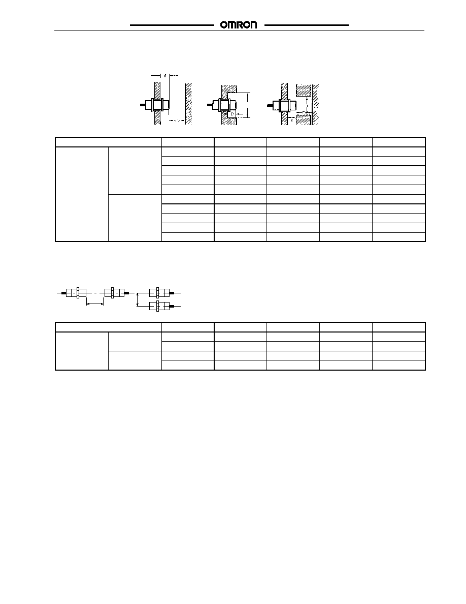
J
EFFECTS OF SURROUNDING METAL
When mounting the E2E within a metal panel, ensure that the clearances given in the following table are maintained. Failure to maintain these
distances may cause deterioration in the performance of the sensor.
d dia.
Type
Dimension
M8
M12
M18
M30
E2E -X j Dj
Shielded
0 mm
0 mm
0 mm
0 mm
j j
DC 2-wire
d
8 mm
12 mm
18 mm
30 mm
D
0 mm
0 mm
0 mm
0 mm
m
4.5 mm
8 mm
20 mm
40 mm
n
12 mm
18 mm
27 mm
45 mm
Unshielded
12 mm
15 mm
22 mm
30 mm
d
24 mm
40 mm
70 mm
90 mm
D
12 mm
15 mm
22 mm
30 mm
m
8 mm
20 mm
40 mm
70 mm
n
24 mm
40 mm
70 mm
90 mm
J
MUTUAL INTERFERENCE
When installing two or more Sensors face to face or side by side, ensure that the minimum distances given in the following table are maintained.
A
B
Type
Dimension
M8
M12
M18
M30
E2E -X j Dj
Shielded
A
20 mm
30 (20) mm
50 (30) mm
100 (50) mm
j j
DC 2-wire
B
15 mm
20 (12) mm
35 (18) mm
70 (35) mm
Unshielded
A
80 mm
120 (60) mm
200 (100) mm
300 (100) mm
B
60 mm
100 (50) mm
110 (60) mm
200 (100) mm
Note: The figures in parentheses refer to Sensors operating at different frequencies.

E2E 2-WIRE DC
E2E 2-WIRE DC
20
J
INSTALLATION
Power Reset Time
The Proximity Sensor is ready to operate within 100 ms after power
is supplied. If power supplies are connected to the Proximity Sensor
and load respectively, be sure to supply power to the Proximity Sen-
sor before supplying power to the load.
Power OFF
The Proximity Sensor may output a pulse signal when it is turned off.
Therefore, it is recommended to turn off the load before turning off
the Proximity Sensor.
Power Supply Transformer
When using a DC power supply, make sure that the DC power sup-
ply has an insulated transformer. Do not use a DC power supply with
an auto-transformer.
Sensing Object
Metal Coating:
The sensing distances of the Proximity Sensor vary with the metal
coating on sensing objects.
J
WIRING
High-tension Lines
Wiring through Metal Conduit
If there is a power or high-tension line near the cable of the Proximity
Sensor, wire the cable through an independent metal conduit to pre-
vent against Proximity Sensor damage or malfunctioning.
Cable Tractive Force
Do not pull cable with the tractive forces exceeding the following.
Diameter
Tractive force
4 mm dia. max.
30 N max.
4 mm dia. min.
50 N max.
J
MOUNTING
The Proximity Sensor must not be subjected to excessive shock
with a hammer when it is installed, otherwise the Proximity Sensor
may be damaged or lose its water-resistance.
J
ENVIRONMENT
Water Resistance
Do not use the Proximity Sensor underwater, outdoors, or in the
rain.
Operating Environment
Use the Proximity Sensor within its operating ambient temperature
range and do not use the Proximity Sensor outdoors, in order to
maintain its reliability and life expectancy. Although the Proximity
Sensor is water resistant, a cover to protect the Proximity Sensor
from water or water soluble machining oil is recommended to main-
tain its reliability and life expectancy. Do not use the Proximity Sen-
sor in an environment with chemical gas (e.g., strong alkaline or
acid gasses including nitric, chromic, and concentrated sulfuric acid
gases).
J
CONNECTING LOAD TO DC 2-WIRE SENSOR
Refer to the following before using AC or DC 2-wire Proximity
Sensors.
Surge Protection
Although the Proximity Sensor has a surge absorption circuit, if
there is any machine that has a large surge current (e.g., a motor
or welding machine) near the Proximity Sensor, connect a surge
absorber to the machine.
Leakage Current
When it is OFF, the Proximity Sensor has leakage current. Refer
to Leakage Current Characteristics. In this case, the load is
imposed with a small voltage and the load may not be reset.
Before using the Proximity Sensor, make sure that this voltage is
less than the load reset voltage.
Countermeasures Against Leakage Current
DC 2-wire Models
Connect a bleeder resistor as the bypass for the leakage current
so that the current flowing into the load will be less than the load
reset current.
Load
Bleeder resistor R
Refer to the following to calculate the bleeder resistance and the
allowable power of the bleeder resistor.
R V
S
/(i
R
-- i
OFF
) (k)
P > V
S
2
/R (mW)
P: The allowable power of the bleeder resistor. (The actual
power capacity of the bleeder resistor must be at least a few
times as large as the allowable power of the bleeder resistor.)
i
R
: Leakage current of Sensors (mA)
i
OFF
: Release current of load (mA)
The following resistors are recommended.
12 VDC (supply voltage): A resistor with a resistance of 15 k
maximum and an allowable power of 450 mW minimum 24 VDC
(supply voltage): A resistor with a resistance of 30 k maximum
and an allowable power of 0.1 W minimum
Inrush Current
A load that has a large inrush current (e.g., a lamp or motor) will
damage the Proximity Sensor, in which case connect the load to
the Proximity Sensor through a relay.

E2E 2-WIRE DC
E2E 2-WIRE DC
Cat. No. CEDSAX4 11/01 Specifications subject to change without notice. Printed in U.S.A.
OMRON ELECTRONICS LLC
One East Commerce Drive
Schaumburg, IL 60173
NOTE: DIMENSIONS SHOWN ARE IN MILLIMETERS. To convert millimeters to inches divide by 25.4.
1-800-55-OMRON
OMRON CANADA, INC.
885 Milner Avenue
Scarborough, Ontario M1B 5V8
416-286-6465
R
OMRON ON--LINE
Global -- http://www.omron.com
USA -- http://www.omron.com/oei
Canada -- http://www.omron.com/oci