Document Outline
- Front Page
- Ordering Information
- Specifications
- Operation
- Engineering Data
- Dimensions
- Precautions
- Contacting Omron

E2EY
E2EY
2
Sensor Detects Only
Non-Ferrous Metals
s
Provides long sensing distances for
non-ferrous metals
s
Easy to see operation indicator
s
Shielded for flush mounting in metal
s
Prewired with 2 meters (6.56 ft) of cable
Non-Ferrous Sensing Inductive Prox
E2EY
Description
Part number
Mounting hardware including one
M18 size sensors (supplied with each sensor)
M18-MHWS
pair of metal nuts and washers
Fits M30 size sensors (supplied with each sensor)
M30-MHWS
s
REPLACEMENT PARTS
Description
Part number
Mounting brackets
Fits M18 size sensors
Y92E-B18
Fits M30 size sensors
Y92E-B30
Protective covers
Fits M18 size sensors
Y92E-E18-2
for shielded sensors
Fits M30 size sensors
Y92E-E30-2
s
ACCESSORIES
Sensing head
Detecting distance
Output
Part number
M18
4 mm (0.16 in)
NPN-NO
E2EY-X4C1
M30
8 mm (0.31 in)
E2EY-X8C1
s
SENSORS
Ordering Information

3
E2EY
E2EY
Specifications
Part number
E2EY-X4C1
E2EY-X8C1
Sensor type
Inductive proximity sensor
Body
Size
M18
M30
Type
Shielded
Supply voltage
10 to 30 VDC, max. ripple 10% peak-to-peak
Current consumption
20 mA max.
Detectable object type
Non-ferrous metals
Effective detecting distance
4 mm
8 mm
(with standard target)
(0.16 in)
(0.31 in)
Usable detecting range
0 to 2.8 mm
0 to 5.6 mm
(with standard target)
(0 to 0.11 in)
(0 to 0.22 in)
Standard target size
18 x 18 x 1 mm
30 x 30 x 1 mm
aluminum, L x W x H)
(0.71 x 0.71 x 0.04 in)
(1.18 x 1.18 x 0.04 in)
Differential travel
20% max. of effective detecting distance
Control
DC
Type
NPN-NO open collector
output
solid-
Max. load
100 mA max.
state
Max. on-state
2 VDC (See graph in Engineering Data section)
voltage drop
Response frequency
70 Hz
Circuit protection
Output short circuit, surge voltage, reverse polarity
Indicators
Target present (red LED)
Materials
Housing
Nickel-plated brass
Sensing face
ABS
Mounting
Two M18 nuts included.
Two M30 nuts included.
Bracket Y92E-B18 optional.
Bracket Y92E-B30 optional.
Connections
Prewired
3-conductor cable, 2 m (6.56 ft) length
Weight
140 g (5.5 oz.)
190 g (7.5 oz.)
Enclosure
UL
--
ratings
NEMA
1, 3, 4, 6, 12, 13
IEC 144
IP67
Approvals
UL
--
CSA
--
Ambient operating temperature
-10
�
to 55
�
C (14
�
to 131
�
F)
Vibration
10 to 55 Hz, 1.5 mm (0.06 in) double amplitude for 2 hours each in X, Y, and Z directions
NO
s
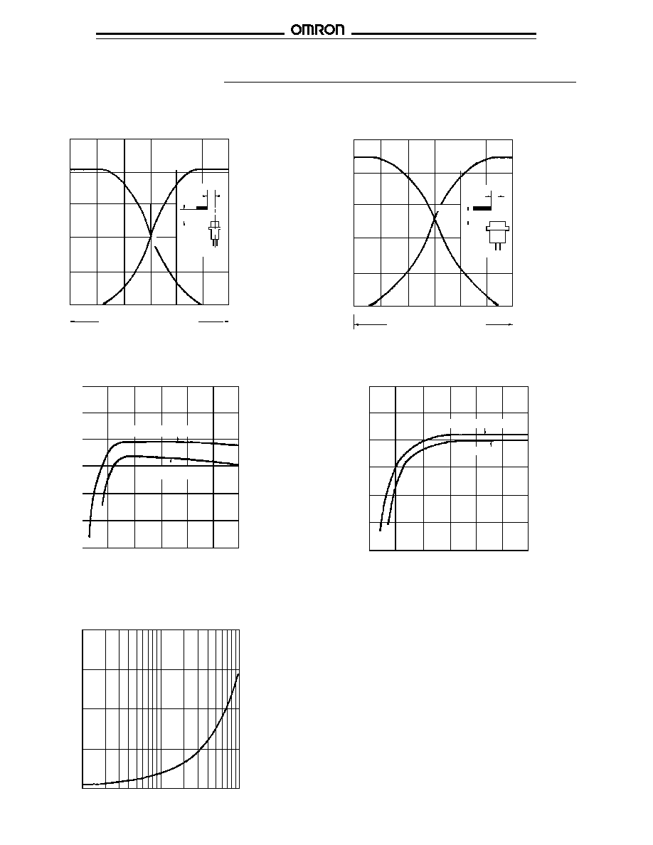
TIMING CHARTS
Target
Output transistor (load)
Operation indicator (LED)
Present
Absent
ON
OFF
ON
OFF
s
OUTPUT CIRCUIT DIAGRAMS AND
CONNECTIONS
NPN Output Type
Red (Brown)
Proximity
switch
main
circuit
100
Output
+V
0 V
White
(Black)
Black (Blue)
Note: IEC colors are shown in parentheses.
Load
Load current
100 mA max.
Operation
E2EY
E2EY
4
Engineering Data
s
OPERATING RANGE
s
SENSING DISTANCE vs. SIZE AND MATERIAL OF TARGET
Sensing
distance
X (mm)
E2EY-X4
Y
X
E2EY-X8
X
Y
Sensing
distance
X (mm)
10
8
6
4
2
-15
-10
-5
0
5
10
15
Sensing Head Diameter
Y (mm)
6
5
4
3
2
1
0
10
20
30
40
50
60
Length of sensed object d (mm)
Sensing distance X (mm)
E2EY-X4
E2EY-X8
12
10
8
6
4
2
0
10
20
30
40
50
60
Length of sensed object d (mm)
Sensing distance X (mm)
Aluminum, copper, brass
Stainless steel
s
ON-STATE VOLTAGE DROP
E2EY
10
8
6
4
2
-15
-10
-5
0
5
10
15
Load current (mA)
Residual voltage (V)
5
4
3
2
1
-9
-6
-3
0
3
6
9
Sensing Head Diameter
Y (mm)
Aluminum, copper, brass
Stainless steel
5
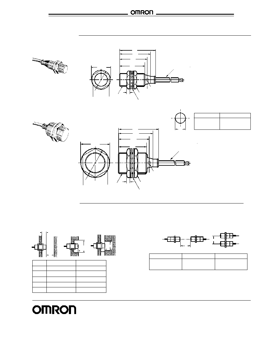
E2EY
E2EY
Model
E2EY-X4C1
E2EY-X8C1
l
0 mm
0 mm
d
18 mm (0.71 in)
30 mm (1.18 in)
D
0
0
m
20 mm (0.79 in)
40 mm (1.57 in)
n
27 mm (1.06 in)
45 mm (1.77 in)
Dimensions
Two toothed washers
42
45
52
60
Operating indicator
5
Two clamping nuts
Two toothed washers
Cable
6 mm OD, 2 m length
42 dia.
M30 x 1.5
36 across flats
E2EY-X8C1
60
Cable
6 mm OD, 2 m length
52
29 dia.
45
42
Operating indicator
Two clamping nuts
4
E2EY-X4C1
Unit: mm
A
B
m
l
D
l
n
m
Model
A
B
E2EY-X4C1
50 mm (1.97 in)
35 mm (1.38 in)
E2EY-X8C1
100 mm (3.94 in)
70 mm (2.76 in)
s
MUTUAL INTERFERENCE
To prevent mutual inference between two sensors mounted
opposite or parallel to each other, be sure to space the two
sensors at a distance greater than that shown here.
s
EFFECTS OF SURROUNDING METAL
When mounting a proximity sensor flush with a metallic panel,
provide the minimum distance shown. This prevents the sensor
from being affected by metallic objects other than the target.
Precautions
M18 x 1
24
across flats
Model
Diameter
E2EV-X4C1
18.5 mm (0.73 in)
E2EV-X8C1
30.5 mm (1.20 in)
F
Mounting holes
OMRON ELECTRONICS LLC
OMRON CANADA, INC.
One East Commerce Drive
885 Milner Avenue
Schaumburg, IL 60173
Scarborough, Ontario M1B 5V8
1-800-55-OMRON
416-286-6465
Cat. No. CEDSAX4
11/01
Specifications subject to change without notice.
Printed in the U.S.A.
OMRON ON-LINE
Global - http://www.omron.com
USA - http://www.omron.com/oei
Canada - http://www.omron.com/oci